Help with Doug Self LED Meter

Thread Starter

danotaur

Joined Sep 8, 2016
7
Hello,

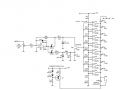
I'm looking to make an LED Bargraph meter for a microphone preamp. I used Doug Self's simple meter in Small Signal Design (the example is attached) and added two extra LED's at the top of the meter so the indicators relate from -14dBu to +4dBu in 2dB increments. The only other difference is that I'm using +/-18 VDC rails. The IC's used are 2901's, here is a link to the datasheet, http://www.ti.com/lit/ds/symlink/lm2901.pdf.

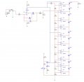
I recreated the circuit in Multi-Sim (example attached) and then made a prototype to put the idea to the test. After some experimentation getting the resistor ladder correct the issue I'm unable to figure out is that the LED at the top of the ladder (with the cathode tied directly to the negative rail) is latched on whether signal is present or not. The LED second from the top won't light up at all. Also, when the 8th LED lights up (0dBu) the LED's dim.

The first 8 LED's seem to work just fine.

I'm guessing that the LED staying on has to do with the comparator output being more positive at the anode than the cathode which is tied directly to the negative rail but I really don't know.

Any help would be greatly appreciated.

Thanks!

Daniel
 

Attachments

danadak

Joined Mar 10, 2018
4,057
The LM2901 worst case common mode input range is Vcc -2 >= Vin >= ground

Are you violating the Vin <= Vcc - 2 spec ?

Regards, Dana.
 

ebeowulf17

Joined Aug 12, 2014
3,307
Hello,

I'm looking to make an LED Bargraph meter for a microphone preamp. I used Doug Self's simple meter in Small Signal Design (the example is attached) and added two extra LED's at the top of the meter so the indicators relate from -14dBu to +4dBu in 2dB increments. The only other difference is that I'm using +/-18 VDC rails. The IC's used are 2901's, here is a link to the datasheet, http://www.ti.com/lit/ds/symlink/lm2901.pdf.

I recreated the circuit in Multi-Sim (example attached) and then made a prototype to put the idea to the test. After some experimentation getting the resistor ladder correct the issue I'm unable to figure out is that the LED at the top of the ladder (with the cathode tied directly to the negative rail) is latched on whether signal is present or not. The LED second from the top won't light up at all. Also, when the 8th LED lights up (0dBu) the LED's dim.

The first 8 LED's seem to work just fine.

I'm guessing that the LED staying on has to do with the comparator output being more positive at the anode than the cathode which is tied directly to the negative rail but I really don't know.

Any help would be greatly appreciated.

Thanks!

Daniel
I'm relatively new to all this, so maybe there's a reason I'm not seeing that this is ok, but it looks wrong to me having those LEDs with no resistors. Is current limited only by the short circuit current of the op amp?
 

ebeowulf17

Joined Aug 12, 2014
3,307
Looks like a constant current source in series with the LEDs.
Thank you! It's all making a lot more sense with fresh eyes now.

It's pretty astounding how badly I was mis-interpreting that circuit the first time I looked at it. I think I get it now. Among other things, I mostly deal with op-amps or a rare breed of push-pull comparators, so I often forget that most comparators have open collector outputs. That schematic made a lot less sense to me with push-pull outputs on every amp!!!
 

Thread Starter

danotaur

Joined Sep 8, 2016
7
The LM2901 worst case common mode input range is Vcc -2 >= Vin >= ground

Are you violating the Vin <= Vcc - 2 spec ?

Regards, Dana.

Thank you for the reply, the inverting inputs that correlate to the two problematic LED's are at +8.9V and +11.4V so I think that is OK. The non inverting inputs are above 0V until signal hits and then those voltages are just over the +8.9 and 11.4V to trigger the comparator.

The outputs for those two comparators, connected to the anodes of the last two LED's, have negative voltages on them which doesn't seem right. That is due to the negative rail directly connected right? Is there a current issue I'm missing that is causing this issue?

Really appreciate the feedback.
 

MisterBill2

Joined Jan 23, 2018
27,462
The first thing that I see is that the 18 volt supply rails are above the +/- 15 volt ratings of the IC devices. Exceeding the max voltage limits will often result in unanticipated operations. This is in addition to all the other comments.
 

Thread Starter

danotaur

Joined Sep 8, 2016
7
Thank you for the replies.

I figured out the problem, I was running the IC's single rail. The data sheet and implementations of the 2901 I found online defaulted to single rail so thats what I went with. Once I switched to dual rail the meter worked great, except for the 2.2uF cap, it's way too big for any meaningful LED metering.

The datasheet says they can run +/- 18V so I hope that is true, the rails are closer to +/-17.

I appreciate all the help everyone, take care.
 

AnalogKid

Joined Aug 1, 2013
12,118
The first thing that I see is that the 18 volt supply rails are above the +/- 15 volt ratings of the IC devices.
upload_2018-6-4_12-27-30.png

36 V total supply voltage is listed under Absolute Maximum Ratings, and there is no separate operating voltage range in the tables. However, in the Electrical Characteristics tables, the supply current is listed for +36 V operation. Also, some of the plots show operation above 30 V.

ak
 
Last edited:

MisterBill2

Joined Jan 23, 2018
27,462
OK, so +/- !8 volts is the abs max limit. But quite a few devices are happier running at +/- 15 volts, and running at the abs max limit is not something that I would choose to do because of possible linearity problems. And not all devices with the same number are really identical.
 

Thread Starter

danotaur

Joined Sep 8, 2016
7
Ok interesting, I would have thought that if they list +/-18V then the devices would function fine to those limits. It won't be hard to drop the rails down.

Thanks for the insight.
 

AnalogKid

Joined Aug 1, 2013
12,118
Most of these parts were developed originally on a 60 V linear bipolar production line. Many opamps of the same period were rated for 44 V operation. As above, the reason for the lower voltage rating might have to do with some performance parameter becoming too high to sell, as opposed to overall device reliability.

ak
 

MisterBill2

Joined Jan 23, 2018
27,462
What is bothering me about the posted circuits is that with all of the comparators off there is over 30 volts across that string of LEDs with a constant current source limiting the current. Or is that the intended mode of operation? This is a lot different from the application circuits for the LM3914 and LM3915 bar graph ICs. Perhaps I need to go and analyze the circuit for a while. I am not at all familiar with Doug Self, or his legacy.
 
Top