 Facebook
 Google
 GitHub
 Linkedin
I know how a multiplexer and demultiplexer work theoretically, I would like some help to connect the theoretical knowledge with these particular circuits (see attached pictures). To be more specific I want to understand exactly what the inputs and outputs on them are. Here's how they look:
Demultiplexer 74HC139 ___________ Multiplexer 74HC153


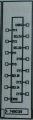
This is how they actually look at the circuit board, so this are the connections I need to understand.
I have looked at the data sheets for these components and written down the names of all the connections (as they are given above), and what I think they mean. Please correct me if I have made some misstake:
Demultiplexer:
So first of all, here there seems to be two of each connection type. Also when looking at the circuit diagram in the data sheet (page two) there seems to be two independent circuits. Does this mean this is actually two demultiplexers in one component? So if I want to only use one demux, it's enough that I use the connections that has a "1" in them, and ignore all connections with "2" in them?
Multiplexer:
Unlike the demux however, in the circuit diagram for the multiplexer every part is connected to the same circuit, so there doesn't seem to be two separate circuits. However there are still connections named "1" and "2" which gives the impression there are two parts. Looking at the circuit diagram in the data sheet (page 2) it looks like we have the same control signals for both parts. How should this be interpreted? What does the "1" and the "2" represent here? Is this in fact one multiplexer or two?
I appreciate if someone can answer these questions in order to help me understand.
Demultiplexer 74HC139 ___________ Multiplexer 74HC153
This is how they actually look at the circuit board, so this are the connections I need to understand.
I have looked at the data sheets for these components and written down the names of all the connections (as they are given above), and what I think they mean. Please correct me if I have made some misstake:
Demultiplexer:
- 1Y3 - output Y3
- 1Y2 - output Y2
- 1Y1 - output Y1
- 1Y0 - output Y0
- SEL1B - control signal B
- SEL1A - control signal A
- EN1G - enable the demux (1 disable, 0 enable)
- EN2G
- SEL2A
- SEL2B
- 2Y0
- 2Y1
- 2Y2
- 2Y3
So first of all, here there seems to be two of each connection type. Also when looking at the circuit diagram in the data sheet (page two) there seems to be two independent circuits. Does this mean this is actually two demultiplexers in one component? So if I want to only use one demux, it's enough that I use the connections that has a "1" in them, and ignore all connections with "2" in them?
Multiplexer:
- OUT1Y - output Y
- 1CO - input C0
- 1C1 - input C1
- 1C2 - input C2
- 1C3 - input C3
- SELB - control signal B
- ST1G - enable the mux (1 disable, 0 enable)
- ST2G - enable the second mux?
- SELA - control signal A
- 2C3
- 2C2
- 2C1
- 2C0
- OUT2Y
Unlike the demux however, in the circuit diagram for the multiplexer every part is connected to the same circuit, so there doesn't seem to be two separate circuits. However there are still connections named "1" and "2" which gives the impression there are two parts. Looking at the circuit diagram in the data sheet (page 2) it looks like we have the same control signals for both parts. How should this be interpreted? What does the "1" and the "2" represent here? Is this in fact one multiplexer or two?
I appreciate if someone can answer these questions in order to help me understand.
Attachments
-
 80.4 KB Views: 148
 -
 81.5 KB Views: 149
 -
876.9 KB Views: 31
-
1.1 MB Views: 31
Last edited:


