I think you should try some Darlington transistors in there.
This is based on the idea that, if changing the capacitor size isn't allowing enough current, you must have run out of current through the transistors.
Because the 3.3V output can't drive the base of Q1 high enough.
You could try the following circuit mod, but with only a 5.6V supply you're pushing your luck. The downside is that there would be a standby 5mA current if the Odroid output stayed at 3.3V. So make sure its output is kept low whenever possible.
Edit: Adopting Crutschow's suggestion, the top cap C1 can be 'borrowed' and paralleled with C2 to effectively double its value, like this:-
..................
Edit: Adopting Crutschow's suggestion, the top cap C1 can be 'borrowed' and paralleled with C2 to effectively double its value, like this:- View attachment 81967
I could not get the Darlington transistors to work or the 470uf capacitor by itself to work. The extra transistor and resistor did work with either the two capacitors in series or the one by itself.
I did notice almost 5ma standby current. Could I get another pin out of the Odroid to supply this to the positive rail so it wouldn't drain the batteries?
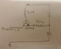
Out of curiosity I tried a different relay and a Raspberry Pi (higher current) and could get the attached circuit mod to work and turn both on or off.
I have a basic IC question I can't find the answer to. On the output of the Schmitt inverter I measured about 150ma or so current for the one pin that I am using. I think the datasheet lists 24ma. I'm not using the other 6 outputs. Is each pin limited to 24ma? Or if you are using only one pin like in my example can you get 24ma x 6? Or am I just making it put out more current and thereby damaging the IC?
 Facebook
 Google
 GitHub
 Linkedin