
Hi all
I have a circuit i have made and this is 1 output stage for my pcb.
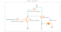
When running the output the transistor heats up quite quickly with no load attached at the mosfet.
See attached image for the schematic where Compressor_Trig_1 is the output from the Atmega pin, Both R17 and R18 have values of 10k and the diode is in flyback configuration.
I'm a bit stumped even in a simulator the currents are quite low 10mA or so even with the 1A load on the output of the mosfet ( Compressor_Out_1)
So am a bit lost as to what the issue is.
The board has 10 outputs and all do this so its not as if it is just a once off thing and also have 5 boards made and they all do it across all of them.
Thanks for the help.
Cheers,
Darcy
I have a circuit i have made and this is 1 output stage for my pcb.
When running the output the transistor heats up quite quickly with no load attached at the mosfet.
See attached image for the schematic where Compressor_Trig_1 is the output from the Atmega pin, Both R17 and R18 have values of 10k and the diode is in flyback configuration.
I'm a bit stumped even in a simulator the currents are quite low 10mA or so even with the 1A load on the output of the mosfet ( Compressor_Out_1)
So am a bit lost as to what the issue is.
The board has 10 outputs and all do this so its not as if it is just a once off thing and also have 5 boards made and they all do it across all of them.
Thanks for the help.
Cheers,
Darcy
Attachments
-
 31.4 KB Views: 47


