 Facebook
 Google
 GitHub
 Linkedin
Hi everyone,
First I would like to introduce and disqualify myself as a electronics hobbyist. I haven't played around with circuits since I built my last Heathkit around 40 years ago!.
I am playing around with a low voltage project mostly for the fun of it, but also to try and cut down some on my electric bill. I am a Fish and Reptile Hobbyist and consume a lot of electricity to enjoy these things. In my terrarium room, I am using Par 38 12 volt lights as basking/heat sources for various cold blooded creatures to use for thermo-regulation. I had the idea to use PV panels to drive the lights directly since I really only need light when the sun is out. I would like to eliminate the use of batteries and PV controllers if possible to keep it simple.
My first tests have gone well and taught me quite a bit. I am using a 140 watt PV panel that has the following specs:
Max Rated Power (Pmax) 140 Watts
Voltage at Max Power (Vmpp) 17.7 Volts
Current at Max Power (Impp) 7.91 Amps
Open Circuit Voltage (Voc) 22.1 Volts
In my very first test, I tried to drive the lamps directly from the panel but the halogen bulbs can't take the voltage and burned really bright for a few hours till they popped.
So I purchased a 360 watt buck converter that gives me a good 12 volts and I can run 3 x 35 watt bulbs and get them the amps they need in full sun, but in the AM, PM, and any cloudy conditions, and the bulbs go completely dim. I note that the voltage does not drop below 12 in these conditions, but the current isn't there to drive them.
In order to get more light in the morning, evening, and cloudy times, that I would like to have some backup power that would provide the current when the PV panels can not.
This is where I have run out of talent") . I don't know if I can simply wire a dc power supply into the input of the buck along with the PV panel inputs, and if I do this, would the lamps pull from current from the power supply instead of the PV Panel. If the voltage of the PV panel is higher than that of the power supply, would this increased "pressure" mean that it would use this current first?
. I don't know if I can simply wire a dc power supply into the input of the buck along with the PV panel inputs, and if I do this, would the lamps pull from current from the power supply instead of the PV Panel. If the voltage of the PV panel is higher than that of the power supply, would this increased "pressure" mean that it would use this current first?
I also considered using a relay to switch from the PV panel to the Power supply, but it would likely have to be triggered by a current sensor since the voltage doesn't drop until its very shaded.
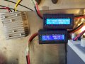
I will stop here for now and see if anyone here is interested in coaching me a little. I have attached the a photo of the two little power analyzers I have been using along with the buck converter. I have one on each side of the converter.
Thanks for taking the time to read this.
Cheers, Lance
First I would like to introduce and disqualify myself as a electronics hobbyist. I haven't played around with circuits since I built my last Heathkit around 40 years ago!.
I am playing around with a low voltage project mostly for the fun of it, but also to try and cut down some on my electric bill. I am a Fish and Reptile Hobbyist and consume a lot of electricity to enjoy these things. In my terrarium room, I am using Par 38 12 volt lights as basking/heat sources for various cold blooded creatures to use for thermo-regulation. I had the idea to use PV panels to drive the lights directly since I really only need light when the sun is out. I would like to eliminate the use of batteries and PV controllers if possible to keep it simple.
My first tests have gone well and taught me quite a bit. I am using a 140 watt PV panel that has the following specs:
Max Rated Power (Pmax) 140 Watts
Voltage at Max Power (Vmpp) 17.7 Volts
Current at Max Power (Impp) 7.91 Amps
Open Circuit Voltage (Voc) 22.1 Volts
In my very first test, I tried to drive the lamps directly from the panel but the halogen bulbs can't take the voltage and burned really bright for a few hours till they popped.
So I purchased a 360 watt buck converter that gives me a good 12 volts and I can run 3 x 35 watt bulbs and get them the amps they need in full sun, but in the AM, PM, and any cloudy conditions, and the bulbs go completely dim. I note that the voltage does not drop below 12 in these conditions, but the current isn't there to drive them.
In order to get more light in the morning, evening, and cloudy times, that I would like to have some backup power that would provide the current when the PV panels can not.
This is where I have run out of talent
. I don't know if I can simply wire a dc power supply into the input of the buck along with the PV panel inputs, and if I do this, would the lamps pull from current from the power supply instead of the PV Panel. If the voltage of the PV panel is higher than that of the power supply, would this increased "pressure" mean that it would use this current first?I also considered using a relay to switch from the PV panel to the Power supply, but it would likely have to be triggered by a current sensor since the voltage doesn't drop until its very shaded.
I will stop here for now and see if anyone here is interested in coaching me a little. I have attached the a photo of the two little power analyzers I have been using along with the buck converter. I have one on each side of the converter.
Thanks for taking the time to read this.
Cheers, Lance
Attachments
-
 491.7 KB Views: 3


