 Facebook
 Google
 GitHub
 Linkedin
I got a beat up Espresso machine that the previous owner explained couldn't wire back together after taking it apart for cleaning. But I am also having some doubts about the autofill controller (Giemme MFC2SN).
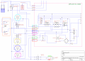
I couldn't find any diagrams or datasheets on the controller so I drew one based on visual and electrical inspection of the board along with the datasheets I found for the material. I've spent a few days looking at everything and double and triple checking, however I'm a little bit too nervous to power on the machine.
According to the diagram on the controller box (CB). Pin 9 should be Neutral and Pin 10 the Hot. However it looks like this would cause a short at Relay 1 between pin 11 ( connected to CB pin 10) and pin 12 ( connected to CB pin 9). Ive been going at this for a few days and can't make sense of it. Im hoping someone can please take a look at the information I have and can help me out.
Here's a list of whats on the control board that's switching the AC.
- Stepdown Transformer: Hahn BV EI 304 3332.
- Relay 1: Finder 40.31S
- Relay 2: Finder 40.52S
- Relay 3: Finder 40.61S
- Varistor: Epcos S07 K175
Attachments
-
 160.7 KB Views: 26
 -
 272.9 KB Views: 35
 -
 134.4 KB Views: 24
 -
306.3 KB Views: 8


