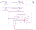
Help need understanding circuit, transformer tap changer? Schmitt trigger?

Thread Starter

Big_Earl619

Joined Jan 9, 2014
12
Hi Everyone,

I was given this circuit to test as a tap changer for a transformer with an output that has 4 configurations based on how the two SPDT relays are switched. The goal is to bring the voltage down as the output current goes up. I don't understand how the circuit works, its seems as if the npn transistors never come on. When simulating I see a drop in voltage when load goes up but there are spikes on the output voltage.

Please help... thanks
1707335380798.png

1707335408603.png


When the load is a short circuit, output is 8V dc

1707335483189.png


When the load is 1k ohms, output is 30v dc

1707335566106.png
 

MisterBill2

Joined Jan 23, 2018
19,588
I see no inputs to the controlling circuit, which that circuit does not make sense to me anyway. So there is no reason why the state of any devices should change.
 

Thread Starter

Big_Earl619

Joined Jan 9, 2014
12
I see no inputs to the controlling circuit, which that circuit does not make sense to me anyway. So there is no reason why the state of any devices should change.
Sorry circuit was corrected, the negative output of the rectifier goes to R20 and R21 as input for the op amp. I get the same results

1707361967754.png
 

MisterBill2

Joined Jan 23, 2018
19,588
I examine the corrected circuit as shown in post #3 and it is still not clear to me. I know what tap changers are supposed to do and what they are intended to accomplish, but how this one does it is not clear. Probably not seeing where the power leaves makes it less clear.
 

LowQCab

Joined Nov 6, 2012
4,346
"" I was given this circuit to test as a tap changer for a transformer ............. ""

If the Hardware or Components for this crude device do not yet exist as a
complete, ( but maybe used to be sorta-kinda functional ), Power-Supply,
all those Relay-Contacts are certainly not the best way to go-about fixing the problem.

Relays can not deliver seamless and timely Voltage-Regulation.

Three back-to-back MOSFET pairs can deliver virtually noiseless switching,
and could even be set-up to automatically reduce-or-boost the Mains-Input-Voltage when needed.

More detailed information is required to arrive at the best solution.
.
.
.
 

schmitt trigger

Joined Jul 12, 2010
966
The forum rules states: be courteous when replying.
I’ll attempt to be as courteous as possible: that is not a functional schematic, it has way too many errors, I wouldn’t know where to start listing them.
 

MisterBill2

Joined Jan 23, 2018
19,588
On a very hot summer day several years back I did amuse myself by watching the results of a tap-changing system working to protect the power distribution equipment that was operating beyond its limits. The voltage would drop in one volt steps over a time of about 3 minutes, in an attempt to reduce the wattage out of the transformer. so it would step down from about 117 volts down to about 110 volts, in one volt steps, at regular intervals of about 15 seconds. When it got to the bottom it would wait about a minute or two, then jump back up to 117 volts and repeat the process..
This was in a rather rural setting, about ten miles from any town.
 

Art Mezins

Joined May 26, 2019
11
I've never encountered such a hybrid relay circuit in my 40+ years of experience and I saw some bizarre relay circuits at Vendo.

The only type of load that can perform as desired is a purely resistive, non-reactive load. I have an 4 year old window A/C that is supposed to be 12A nominal at 110VAC, but it gets up to 18A when the voltage drops on a hot day (e.g. >100 degF). That higher current makes the AC line voltage drop which makes the motor draw more current since it tries to maintain constant power.

It may be easier to "simply" describe what you want this circuit to do by fully describing the environment inputs and expected outputs (as best as you can). I did notice that the choice of the LM101 was needed, since that is one of the few older op amps that supported a full-range differential input operation (e.g. 30V range at +/-15V), but it's unclear if it's does that with a unipolar 5V supply. Other op amps outputs "flip" when their differential input is exceeded.
 
Top