(Help) Modded PSU issue part 2

Thread Starter

Nikola Zlatkov

Joined Aug 22, 2017
12
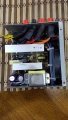
So I modded a psu into a bench test supply, and I put a dummy load of 5 ohms on the 5v rail, and the psu would shut itself down after 20 seconds. Then I put a 22 ohm resistor on the 12v rail instead, the psu turned itself off after less than 10 seconds. Then I tried both resistors at the same time and it still turns off. Am I missing something or is the supply busted?
 

Marcus2012

Joined Feb 22, 2015
425
Hi

You're probably tripping the over/under-voltage protection in the circuit when you apply a load. What you need to do is disable undervoltage protection and then ground and isolate the Overcurrent sense pins so it is impossible for the voltage to trip out. Overcurrent protection is a legal requirement, undervoltage protection is not so the IC you use in the ATX PSU should have a datasheet explaining pinout and how to disable undervoltage protection.
 
Last edited:

Reloadron

Joined Jan 15, 2015
7,501
You may want to see what the PWR_OK line is doing. Should be Pin 8 and Gray wire. When the PSU starts and does its own self test it should send a PWR_OK out on pin 8 in the form of going from 0V to 5V. I assume that for Start you are simply placing pin 16 of a 24 pin or pin 14 of a 20 pin connector to Ground, typically the green wire. Depending on the age of the PSU I have read variations where some claim it regulates off the 3.3 volt supply, others claim the 12 voly supply and finally some claim the 5 volt supply, depending on what I read and how old the PSU is. I would see if the PWR_OK line is going high.

Ron
 

Thread Starter

Nikola Zlatkov

Joined Aug 22, 2017
12
You may want to see what the PWR_OK line is doing. Should be Pin 8 and Gray wire. When the PSU starts and does its own self test it should send a PWR_OK out on pin 8 in the form of going from 0V to 5V. I assume that for Start you are simply placing pin 16 of a 24 pin or pin 14 of a 20 pin connector to Ground, typically the green wire. Depending on the age of the PSU I have read variations where some claim it regulates off the 3.3 volt supply, others claim the 12 voly supply and finally some claim the 5 volt supply, depending on what I read and how old the PSU is. I would see if the PWR_OK line is going high.

Ron
I have an led on purple to ground, and on grey to ground to check if the psu is on standby or on. When I plug the supply the standby led lights up, when i flip the switch for green to ground, the grey wire led lights up. The supply runs for a little and the grey wire led turns off. Can you be more specific for what i should do I'm kind of a novice :(
 

Reloadron

Joined Jan 15, 2015
7,501
Since that PWR_OK Line is going low my guess is the PSU is seeing something it does not like. The load resistors you are using should not cause a shutdown, they should be fine. If I had to guess and I am taking a guess that the PSU may be faulty. I can't see what it would not work. There are dozens of tutorials out there on how to make an ATX form factor PSU into a bench supply and what you are doing should work fine.

Ron
 

Marcus2012

Joined Feb 22, 2015
425
Last edited:

Thread Starter

Nikola Zlatkov

Joined Aug 22, 2017
12
Never mind I've just seen your original thread your resistors are fine. I had this problem with mine, when you run an inductive load on it the current will peak for a fraction of a second (inrush current). You need to disable under voltage protection and ground and isolate the over voltage protection sense pins of the IC.

3D Printer ATX Power Supply Fix
ATX Power Supply Modification – Defeating Over-Current Shutdown
Thanks, that will probably do the trick, but like I said I'm a novice so I'm not sure what exactly am I supposed to ground. I will check some data sheets for components on my supply. I am guessing that I wont be needing a dummy load, tho if I short the supply it's probably going to fry some components.
 

Attachments

Marcus2012

Joined Feb 22, 2015
425
No, no dummy load needed for this, just information and some pin adjustment. Basically an ATX PSU needs to have very fine tolerances for voltage fluctuations as it is powering a computer's logic levels. For the protection of the computer and consumer Over and Under voltage protection (OVP/UVP) are added to cutoff power if the levels fluctuate too wildly. Over voltage protection is on all ATX PWM Controllers but undervoltage protection is sometimes absent or disabled (or can be disabled). Your ATX PWM Controller (the only IC in there iirc) will have an associated datasheet with pinout diagrams explaining this. As an example I will explain my one. My ATX PWM Controller is a SDC2921 (datasheet attached). As you can see pins 1-3 are "OVP/UVP input for 3.3V/5V/12V" respectively, this is the ICs way of monitoring voltage outputs. Now if we scroll down we come across the vital information about pin 4 (page 10).

"The function of PT


This signal is prepared for extra OVP/OPP (VPT > 1.25V) or disables under voltage protection function (VPT < 0.62V) "

So if I isolate pin 4 (if it isn't already) and attach it to ground, voila! undervoltage protection disabled.
Now the pesky Over voltage protection. Remember the sense pins 1-3? Well as we can no longer have any undervoltage cutout (we disabled it) we isolate them (cut their existing connections) and tie them all to ground. It is now impossible for the IC to detect an "over voltage" as it can only ever be at ground value (0V). Problem solved! :)

The hardest part is determining what ATX PWM controller you have as it is most likely Chinese and has poor English documentation and I cannot make it out in the photographs.

Hope that helps :)

EDIT: Unrelated to the above, you still will need a dummy load on the 5V output but I would suggest a higher value, at the moment your 5R will draw 1A which is way more than you need. Go with a 10-20R @5-10W and that should be better (between 0.25-0.5A)
 

Attachments

Last edited:
Top