Help me Battery current limiting circuit with UC3842

Thread Starter

AKFD

Joined Apr 14, 2025
73
As I look at the circuit operation it becomed clear that this charging scheme is capable of producing radiated harmonics that may exceed the allowable levels.

What that means is that after you finally get it working, if this is intended to be a commercial product, you need to address that aspect as well.
If it is a single system for personal use only, probably those rules would not apply.
So how do we eliminate radiated harmonic waves?
Can adding an RC snubber circuit across the MOSFET's Drain-Source terminals eliminate them?
 

ronsimpson

Joined Oct 7, 2019
4,809
Much of the RF noise from a PWM is in how the PCB is designed out. I think you are not ready to think about this.
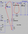
There is a loop D2, L2, C7. This must be as small as possible.
Another loop C4, Q1, R1. This must be as small as possible. Use wide heavy traces.
One more. IC-Gate of mosfet, R8, Q1, R1, and ground back to the IC. Keep R8 at the Gate of the MOSFET.
1789780929248.png
Most everything is low frequency or low power.
 
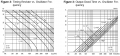
R1 is also known as Rt. Here is a graph on Rt, Ct and frequency.
By using this circuit, you changed from a current mode PWM to a voltage mode. The PWM is not watching the MOSFET current. This circuit makes a waveform but is not really watching current or voltage.
1789863137587.png
 

ronsimpson

Joined Oct 7, 2019
4,809
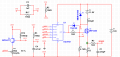
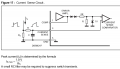
If you do not use Q4 circuit; the voltage across R6 will have a peak voltage of 1V, when the error amplifier is not used, like you show.
R6 = 1 ohm will only give you less than 1A.
With Q4 and R13, the voltage at SENSE depends on how R13 is adjusted + the voltage across R6.
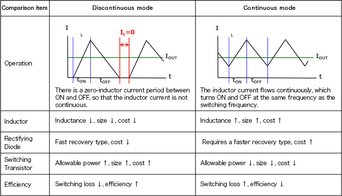
There are two different modes a PWM can run in. In you case Discontinuous mode the inductor current starts out at 0A and ramps up to 1A. Then it ramps down to 0A. There is a short time at 0A. (1 ohm, 1V, 1A) In Continuous mode, the current starts out at some amount. In the picture it looks like about 0.5A. It ramps up to 1A, then back down. The current never reaches Zero.
 
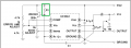
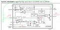
The IC was designed to monitor the MOSFET current on pin-3. In most applications the current ramps up starting at 0A. If the voltage at pin-3 reaches 1V the OutPut will be turned off. When the power supply is in regulation the error amp's output will drop down and make pin-3 voltage less. Look at the "current sense comparator". One input goes to the current sense resistor at the bottom of the MOSFET. The other input goes to the error amp. The error amp sets the turn off current. At light loads the error amp might tell the Current Sense Comparator to turn off at 0.13V. This will make the current much smaller.
1790046182926.png
Another picture.
1790046800014.png
 
Top