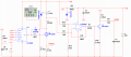
I think you are charging a 12V battery from a 18V power source.
It looks like there is no "max voltage" function. Full charge. By looking at the voltage across V2 you could stop/reduce the charging current when the voltage is too high.
As the V2 voltage get high you might hit the max duty cycle of the IC. This will limit the full charge voltage.
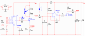
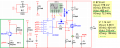
Current is measured by R6, which is the MOSFET current. (Average current 3.24A?)
I think you are charging a 12V battery from a 18V power source.
It looks like there is no "max voltage" function. Full charge. By looking at the voltage across V2 you could stop/reduce the charging current when the voltage is too high.
As the V2 voltage get high you might hit the max duty cycle of the IC. This will limit the full charge voltage.
Current is measured by R6, which is the MOSFET current. (Average current 3.24A?)
I am designing a battery charger ranging from 11.8V to 14.4V. The DC current through MOSFET Q1 is 3.24A. In practice, the actual battery voltage can be higher, for example, 12.8V.
So can my circuit be used? The 14.4V charge cutoff feature will be designed later.
My current circuit is just for testing whether the principle is correct.
I have not tried your circuit. It looks like the error amplifier is responding too fast. You might try making C10 100nF and see if the duty cycle becomes stable.
You have added two further amplifier stages each with its own RC network, each will shift the phase 90°, so you have made an oscillator.
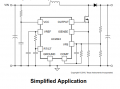
Why not use the error amplifier in the UC3842. That's why it has one. Join the SENSE pin to the current sense resistor, and let it do its job,
I have a project to drive 3A into an LED. So, I modified the schematic to get 3A into a battery.
The battery is C7, R12 and D1.
Current is set by R1 and the voltage on "COMP" pin of U1. If COMP=5V then the current is 3A.
Over voltage protection is set by Q3. If the voltage is too high the "FB" pin is pulled up which reduces the current by pulling down COMP.
This is not a normal PWM way of using the IC. It is a constant off time controller. Any time Q1 (big MOSFET) is on then Q2 (very small MOSFET) is also on, which crushes the oscillator in the UC3843. In this mode the IC turns on Q1 until the current reaches the desired level. Now the MOSFETs are turned off. There is a dead time set by R3 & C1. Then the next cycle starts.
I attached the LTspice file.
You have added two further amplifier stages each with its own RC network, each will shift the phase 90°, so you have made an oscillator.
Why not use the error amplifier in the UC3842. That's why it has one. Join the SENSE pin to the current sense resistor, and let it do its job,
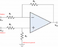
Start out with a differential amplifier. (Vtop of battery) - (Vbottom end of battery) reference it to ground. The output of this op-amplifier is the battery voltage but from 0 to 12V. Now divide down to 2.5V where the UC3842 regulates. Most car batteries should be limited to 14V so set the circuit so 14V of the battery causes 2.5 on the FB pin of the IC. The current will fall back when the voltage gets too high.
This is much like Q3 in post #6.
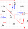
R11=1k. Gain is set by R10,R12 also R2,R11. With a gain of 1 the battery voltage will appear on the output of the op-amp.
What do you want to do when the battery is charged.
1) Stop all charging and shutdown. or
2) Reduce the current and keep the voltage at some level. (post #6) or
3) Drop back to trickle charge. (50mA?)
With out knowing this we can't help much.
I have a project to drive 3A into an LED. So, I modified the schematic to get 3A into a battery.
The battery is C7, R12 and D1.
Current is set by R1 and the voltage on "COMP" pin of U1. If COMP=5V then the current is 3A.
Over voltage protection is set by Q3. If the voltage is too high the "FB" pin is pulled up which reduces the current by pulling down COMP.
This is not a normal PWM way of using the IC. It is a constant off time controller. Any time Q1 (big MOSFET) is on then Q2 (very small MOSFET) is also on, which crushes the oscillator in the UC3843. In this mode the IC turns on Q1 until the current reaches the desired level. Now the MOSFETs are turned off. There is a dead time set by R3 & C1. Then the next cycle starts. View attachment 371346
I attached the LTspice file.
Neat. I'd not thought of that. Constant Off Time is less prone to sub-harmonics oscillations than normal PWM. I wonder if you could do constant on time - that has the advantage of slowing down and reducing switching losses at low power.
The CU384x series had a Hysteresis control that I really liked but no one used it but me. LOL So, it was discontinued. It would work very well here. It turns on and off at set amounts of inductor current. For example, it turns off at 3.3A and back on at 3.0A. The error amplifier moves the 3.3/3.0A point up or down to control the power. It is not constant frequency. For battery charging the hysteresis and the constant off time work much the same.
The title of this thread is about battery charging current limiting. The actual charging scheme depends quite a bit on the chemistry of the battery type to be charged. I don't think that the battery type has been mentioned. OR, is this design intended to be a universal battery charger??
(12V lead-acid battery )
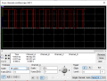
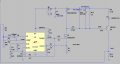
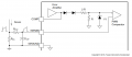
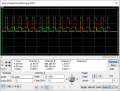
According to the datasheet, I added the blue circuit block, and the clock signal is smooth and stable.
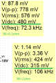
Based on the diagram, why does changing R6 cause VDC to also change instead of staying constant (the VDC voltage at the blue circled area)?
It certainly looks like R6 is used as a "current sense" resistance in the circuit shown. BUT it is also a big part of the current controling (limiting) resistance in that circuit. That is part of the reason.
In addition, the Vgs, which controls the current, is also affected by the current thru R6.
You ask about why 480mV changed to 315mV. I think you should be asking about why 778mVp-p changed to 3,360mV.
Why the frequency is different? Too many things change to know without seeing a closeup picture of that waveform(s).
With the new Q4 circuit the current ramp seen on SENSE is distorted. The IC will act differently.
You ask about why 480mV changed to 315mV. I think you should be asking about why 778mVp-p changed to 3,360mV.
Why the frequency is different? Too many things change to know without seeing a closeup picture of that waveform(s).
The design of a good battery charger is rather complex. Your design falls into the simple category at this stage ( some voltage and current control). If you want something more sophisticated, use the current power circuit and add a micro to do some smarts.
As I look at the circuit operation it becomed clear that this charging scheme is capable of producing radiated harmonics that may exceed the allowable levels.
What that means is that after you finally get it working, if this is intended to be a commercial product, you need to address that aspect as well.
If it is a single system for personal use only, probably those rules would not apply.

 Facebook
 Google
 GitHub
 Linkedin