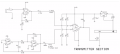
In following circuit, I don't understand effects of resistors R6,R7,R8,R9,R10. Can you explain for me? How does this circuit work without these resistors? Thank you for help
This being the homework section, think about this.
1. What is the voltage at the junction of R6 and R7?
2. What is the voltage at the junction of R8 and R9?
3. View the schematic of the LM311 and tell me about the output circuitry?
This being the homework section, think about this.
1. What is the voltage at the junction of R6 and R7?
2. What is the voltage at the junction of R8 and R9?
3. View the schematic of the LM311 and tell me about the output circuitry?
I think that R6 and R7 form the voltage divider. Vjunction=R7/(R6+R7)*Vcc. When V+>V-, Vout jump up to positive saturation approximate Vcc. When V+<V-, Vout from positive saturation to zero. However, i don't understand effect of Vjuntion. I know that a simplest comparator is only a op-amp. It can work without any resistors.
As far as I can tell the resistors form voltage dividers. The purpose of the voltage divider is to provide dc offset for the signals coming out of the TL chips. I notice capacitors between TL chips and LM311, I am guessing those are dc blocking capacitors. So the signals are coming out of TL chips, their dc offsets are removed by the dc blocking capacitors. You want to input those signals to LM311, but you also want to shift them because your LM311 only has one power supply. If you don't shift them up, the part of the signals below 0 volts will be blocked (lost in other words). So the voltage dividers provide the dc offset to the incoming signals, now the incoming signals have room to oscillate between 0 and 9 volts. It looks like voltage dividers divide the 9 volts into two halves. So the incoming signals will oscillate around the 4.5 volts.
Lets say for example that you have incoming signal that is 2 volt peak to peak. It oscillates around 0 volts, from -1 to +1 volts (+1-(-1)=+1+1=2 volts peak to peak). If you feed it straight to LM311 with rails at 0 volts and 9 volts, the part of the signal with voltages from 0 to 1 volt will show, the part of the signal from -1 to 0 volts will be lost because your lowest limit is 0 volts (your lowest rail), there is no room for anything smaller like -1 volts. So you introduce the dc offset of 4.5 volts by means of voltage divider. Now your incoming signal has been shifted up, it oscillates around 4.5 volts, from 3.5 to 5.5 volts (5.5-3.5=2 volts peak to peak).
The reason I wanted to view the youtube video was to see whatever was presented. As it's written on the schematic, the audio will exceed the reference and not produce the proper full scale PWM. I would call this "over-modulated" but I see that the word "over-modulated" is not in the lexicon of digital schemes.

 Facebook
 Google
 GitHub
 Linkedin