Help Interpreting Transformer Wiring Diagram

Thread Starter

Braxton Kalfs

Joined Nov 14, 2019
11
Hello, I am new to the forums and am reaching out to learn how to wire a transformer for a project of mine.

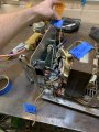
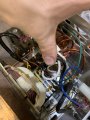
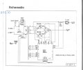
I have an old golf cart charger that I am attempting to use to convert 120 vac to 12vdc. The charger was originally intended to charge multiple 48v batteries.

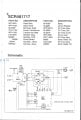
I have found a wiring diagram for the charger but not for the internal transformer itself. In my short research I have learned that this charger uses two rectifiers to convert what I assume to be 48vac into 48vdc

Attached is the diagram for the charger, including it’s more complex circuitry. I wish to wire this as simply as I can.

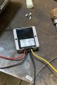
I have purchased a 48vdc to 24vdc converter to use, unless the windings on my transformer cannot be wired for 24v.

I intend to use this project as a 12vdc power supply that I can run off of 120vac.

I am a noobie to this circuitry stuff and would appreciate any help I can get!

Thank you
 

Attachments

drc_567

Joined Dec 29, 2008
1,156
The schematic shows the presence of two selenium controlled rectifiers (SCRs). These parts require a gate signal to turn on. Is it possible that there is some sort of adjustment for the gate signal?
... A snapshot of the phenolic board components may be helpful.
 

BobaMosfet

Joined Jul 1, 2009
2,110
@
Braxton Kalfs

Understand how an SCR works- it is a thyristor. Once the gate is charged, it is ON, whether or not power is applied to the gate again. In order to shut it off, you have to kill power to All 3 terminals (A, K, and G). That is one of the reasons SCRs are used in A/C waveforms.
 

MaxHeadRoom

Joined Jul 18, 2013
28,617
Can you not simply measure the various secondary outputs of the transformer, voltage wise?
It may be possible to modify the secondary as needed.
Max.
 

dendad

Joined Feb 20, 2016
4,451
What current do you need for you 12V supply?
And what is the final application you have in mind? Keep in mind, for instance, a 12V supply is not what you want to charge 12V batteries.
So if you tell us what you want to use it for, that will help a lot.
EDIT:
You may find the transformer secondary voltage a bit high for easy used as it was designed to charge 48V batteries. Adding a bridge rectifier and filter caps to the secondary will probably produce more that 60V DC. Even these have a 60Vin max..
DPS5020 power supply.png

Can you measure the AC out of the transformer?
Then, multiply the reading by 1.4 to give the DC value. Then, whatever regulator you use will have to cope with that. Check your 48V to 24V reg for max input voltage allowed.
 
Last edited:

Thread Starter

Braxton Kalfs

Joined Nov 14, 2019
11
Thank you all for the info!
I plan on measuring the voltage outputs tomorrow.

I am still a bit confused as to why the transformer itself has 4 outputs (A B C D). Two of them are coupled together(B&C).

Does this 48v transformer combine two windings into one

Could someone go more in depth as to how do these SCR work? it sounds like a relay that dose not turn off?
What do (A,K,G) stand for?
How do these help me to turn the AC into DC?

I have attached a few crude photos for reference. I have labeled the output wires based on my originally uploaded schematic

Also attached is a photo of the transformer model number which I could not find and diagrams for. TX16264V1

Thank you, I hope this helps you help me!
 

Attachments

Thread Starter

Braxton Kalfs

Joined Nov 14, 2019
11
My final intention of this supply is to power a winch that I have created a circuit for. Letting me control the direction of the winch using two SPST push button switches and two SPDT relays (Up & Down).

Attached is a photo of my completed circuit and the diagram I used as reference to wire it up.

(Not my drawing, although it serves me well!)
 

Attachments

dendad

Joined Feb 20, 2016
4,451
There are many on line sites to help learn.
http://www.learnabout-electronics.org/PSU/psu10.phphttps://www.allaboutcircuits.com/textbook/These are just 2 examples.
The transformer has multiple outputs, each for a purpose.
The SCRs are rectifiers (pass current on way only) that can be turned on at a specific time in the AC cycle so the output can be controlled. The turn off when the AC input goes to zero.
Someone else may write up a full description of the circuit, but I think you need to spend time reading up on electronics a bit. It is well worth it, and playing with electronics is great fun!
 

dendad

Joined Feb 20, 2016
4,451
Do you have any info on the battery charger, like a back panel specification label? Also, what is the stall current of the 12V winch? You need to see if the charger is capable of supplying enough power to the winch.
 

Thread Starter

Braxton Kalfs

Joined Nov 14, 2019
11
Thanks for the great resources!

Attached are photos of the charger and winch schematics. Along with the photo I meant to include earlier of my existing circuit that I plan on using this supply for, I currently am using a jump box/battery charger to power it for testing.
 

Attachments

dendad

Joined Feb 20, 2016
4,451
Your battery charger transformer core sounds to be big enough to run the winch with a full load.
1.1HP is around 820Watts, and the rating of the charger is similar. But you need to reduce the volts efficiently to preserve the power rating. A switch mode, not linear regulator is required.
It may be easier to get an appropriate lower voltage transformer, but I think that will not be cheap. Unless you want to take a try at rewinding the one you have.
The regulator posted above will not be big enough. You need a 60Amp. or bigger one. And one that can take at least 60VDC input.
What are you intending the winch to do? What will be the load?
 

Thread Starter

Braxton Kalfs

Joined Nov 14, 2019
11
That’s good to hear! This project is mostly repurposed parts. So I would love to make this transformer perform to my needs.

I do not have an intended purpose for the winch just yet. I plan to use it in my shop to either lift things up off the ground or to pull things into the shop.

Attached is a photo of the step down 48VDC to 12VDC transformer that I have purchased for this project
 

Attachments

Thread Starter

Braxton Kalfs

Joined Nov 14, 2019
11
I just did a quick read on my multimeter this morning,

The transformer outputs read as:

A - D 129VAC
A - BC 64VAC
D - BC 64VAC

Which regulator are you referring to?

Thank you
 

Dodgydave

Joined Jun 22, 2012
11,284
Thank you all for the info!
I plan on measuring the voltage outputs tomorrow.

I am still a bit confused as to why the transformer itself has 4 outputs (A B C D). Two of them are coupled together(B&C).

Does this 48v transformer combine two windings into one

Could someone go more in depth as to how do these SCR work? it sounds like a relay that dose not turn off?
What do (A,K,G) stand for?
How do these help me to turn the AC into DC?

I have attached a few crude photos for reference. I have labeled the output wires based on my originally uploaded schematic

Also attached is a photo of the transformer model number which I could not find and diagrams for. TX16264V1

Thank you, I hope this helps you help me!
Looks like a 64 -0-64V transformer with A-bc -D as the windings, SCR is a Thyristor, it has an Anode Cathode and a Gate, it's like a diode that has to be triggered to conduct, the trigger pulse is between the Gate and Cathode, usually about a 1v, these can be delayed triggered to produce lower output voltages, just like a dimmer circuit, once triggered they stay conducting until the voltage decreases to zero..

Your circuit is acting as full wave bridge rectifier using a Centre Tapped transformer, where only one thyristor conducts per half cycle of the mains.


5.jpg
 
Last edited:

dendad

Joined Feb 20, 2016
4,451
The problem is your transformer output voltage it too high for your application. The 48V to 12V converter will go bang I expect.
Without rewinding the transformer, I do not see an easy way for you to use this charger safely. And I doubt the control of the charger is able to be set to work as a 48V supply without voltage overshoots high enough to cause damage to your regulator. Someone else may have more ideas.
 

Thread Starter

Braxton Kalfs

Joined Nov 14, 2019
11
Thank you for the breakdown! And the diagram!

Can I use these SCRs to convert my 64vac secondary’s into 12vdc or even 48vdc without using the trigger pulse (g)?

If not how do I trigger it correctly to receive the desired output?
 

drc_567

Joined Dec 29, 2008
1,156
The schematic shows a 'zero ohm' shunt coil in series with the negative DC output lead ... It appears to be a heavy gauge piece of copper in one of the photos. Just guessing, but the purpose of that coil is to act as a high frequency impedance and smooth out the DC waveform as it goes to the batteries.
 

Thread Starter

Braxton Kalfs

Joined Nov 14, 2019
11
If possible I do not want to use the any of the control circuitry, just the transformer and SCRs, unless something else is needed from the original diagram
 
Top