Help! I need 2 input one output 12v

Thread Starter

learner112

Joined Mar 15, 2025
9
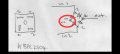
I need something where it has two inputs and one output, so either (1) can be triggered and activate the output or (2) can be triggered and activate output but not backfeed into the opposing trigger source. (If possible asbestos trigger to also block all output, since one trigger source is automatic id like to be able to block the trigger output of that at times)
So a switch is one trigger, automatic trigger, and option to block the output at times i want when the automatic trigger is powered.
 

sagor

Joined Mar 10, 2019
1,046
Your question is not clear. input and output of what? Audio, video, power? More detail about what is being switched and power levels would help. What is to do the "switching". Is the 12V in the title the power being switched, or the voltage used to do the switching?
 

Thread Starter

learner112

Joined Mar 15, 2025
9
Your question is not clear. input and output of what? Audio, video, power? More detail about what is being switched and power levels would help. What is to do the "switching". Is the 12V in the title the power being switched, or the voltage used to do the switching?
Sorry I don't really even know how to ask what I'm trying to do I'm not good with this stuff, but both input triggers are 12v positive power and the output needs to be positive 12v power also.
So the one 12v positive input is automatic, it comes on when a separate sensor is activated, the other 12v positive input would be from a switch. I don't know what i need to control this ( a relay or something?) To put a single positive 12v output when either trigger is activated but not back feed into the other un active trigger, I'd possible I'd like to be able to ad another switch of some sort with either 12v - or + to stop all output even when one of the inputs is triggered, so if the auto input is triggered but i don't want to receive output from (?) Device is can switch it so it wont.
 

sghioto

Joined Dec 31, 2017
8,633
Recommend this Diode
At 10 amps this diode will dissipate appx 5 watts and need to mounted on a heatsink.
There is also appx 0.5 volt loss through the diode.
 

dendad

Joined Feb 20, 2016
4,634
1742093601059.png1742093861948.png
Instead of separate diodes, use a 25A bridge rectifier like this, and bolt it down to the metal chassis for cooling.
This also makes mounting it all easier.
 

dendad

Joined Feb 20, 2016
4,634
The tab with the hole of that diode is the "K"athode, as is one of the leads. If you use the diodes, they will need to be insulated from gnd, not just screwed down to metal for a heat sink. You can either mount both diodes to a heat sink and insulate the heat sink from gnd, (the heat sink then becomes the output) or use insulation kits for the diodes.
1742096223181.png1742096289334.png
The bridge rectifier is a lot easier as you can just screw it down. I doubt the extra voltage loss wil cause any problems.
 

dendad

Joined Feb 20, 2016
4,634
Yes, that is correct.
Using the bridge, just crimp spade terminals onto the wires and push them onto the 3 terminals. The "-" terminal is not used.
 

KarriLee

Joined Mar 16, 2025
11
Throw in a couple of schottky diodes to keep the voltage drop low. If you want dimming when both are on, that’s a whole other setup with relays or resistors and gets complicated fast. Just make sure the diodes can handle the current.
 
Top