 Facebook
 Google
 GitHub
 Linkedin
Hello,
I have an LED cube in the front office at my company. We bought it from a company called Seekway and the only way to write new animations to it is via an SD card. I'd like to control the LED cube myself using a combination of a raspberry pi and some Arduino-type devices. This way we can easily write new animations and maybe even play games on it.
The LED cube is 16 x 16 x 16 pixels and each pixel is an RGB LED. The design of the cube is quite clever. The cube is split up into 32 subsections, and each subsection acts like an LED strip. Each subsection is 16 pixels high and 8 pixels wide. Construction-wise this corresponds to 16 small PCBs, which each have 8 LEDs on them. I've attached some pictures to help facilitate some visual understanding of the construction.
For each subsection, power connections are made through 2 long rods. 5V on one rod, ground on the other. Each PCB gets soldered to these rods which serve as structural members as well. For signal, there is only one wire to each subsection, so I reckon the ICs are similar to those you find on LED strips with similar one-wire interfaces. Bare "wire" is used to connect each PCB to route the 1 wire signal up the subsection.
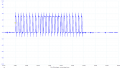
I was hoping to just be able to grab a software library that works on most COTS LED strips and use that to control the cube, but it seems the protocol for the cube's LED strips are a little more complicated. For example, on the simple side, you have the WS2812 IC which takes 3 bytes, displays the corresponding color on your LED, and goes into pass through mode so the next 3 bytes go to the next IC in the strip. I've attached a signal grab of data that goes into a WS2812 LED strip. It's quite compact, and you can see the 24 bits that go into the first IC when I turn it Red.
Thinking I'd see something similar, I cut the signal wire to the topmost PCB in one of the subsections. On this wire, I should be able to see the data that usually goes to the last 8 pixels in the chain. So I loaded up a test animation where the LEDs cycle through Red then Green then Blue. 0 red -> 255 red, 0 green -> 255 green, and then 0 blue -> 255 blue. Then I connected my oscilloscope. This waveform is much less concise, and has 4 sections. First a beginning section that is always the same, next another section that is always the same, THEN a midsection where I can see the changing color data, and an end section that seems to stay the same. It also should be noted, that I see a lot more data than I expected, so it may not act like a regular LED strip but the signal I'm seeing does have some similarities to the WS2812 strip's.
After looking at the IC's package and scouring the internet, I'm unable to identify the IC.
I'm also not able to conclusively identify the protocol being used or what represents a "1" vs a "0" like I can see easily with the WS2812 strip.
Can you help me identify the IC being used, or at least the protocol?
Thanks for reading!
I have an LED cube in the front office at my company. We bought it from a company called Seekway and the only way to write new animations to it is via an SD card. I'd like to control the LED cube myself using a combination of a raspberry pi and some Arduino-type devices. This way we can easily write new animations and maybe even play games on it.
The LED cube is 16 x 16 x 16 pixels and each pixel is an RGB LED. The design of the cube is quite clever. The cube is split up into 32 subsections, and each subsection acts like an LED strip. Each subsection is 16 pixels high and 8 pixels wide. Construction-wise this corresponds to 16 small PCBs, which each have 8 LEDs on them. I've attached some pictures to help facilitate some visual understanding of the construction.
For each subsection, power connections are made through 2 long rods. 5V on one rod, ground on the other. Each PCB gets soldered to these rods which serve as structural members as well. For signal, there is only one wire to each subsection, so I reckon the ICs are similar to those you find on LED strips with similar one-wire interfaces. Bare "wire" is used to connect each PCB to route the 1 wire signal up the subsection.
I was hoping to just be able to grab a software library that works on most COTS LED strips and use that to control the cube, but it seems the protocol for the cube's LED strips are a little more complicated. For example, on the simple side, you have the WS2812 IC which takes 3 bytes, displays the corresponding color on your LED, and goes into pass through mode so the next 3 bytes go to the next IC in the strip. I've attached a signal grab of data that goes into a WS2812 LED strip. It's quite compact, and you can see the 24 bits that go into the first IC when I turn it Red.
Thinking I'd see something similar, I cut the signal wire to the topmost PCB in one of the subsections. On this wire, I should be able to see the data that usually goes to the last 8 pixels in the chain. So I loaded up a test animation where the LEDs cycle through Red then Green then Blue. 0 red -> 255 red, 0 green -> 255 green, and then 0 blue -> 255 blue. Then I connected my oscilloscope. This waveform is much less concise, and has 4 sections. First a beginning section that is always the same, next another section that is always the same, THEN a midsection where I can see the changing color data, and an end section that seems to stay the same. It also should be noted, that I see a lot more data than I expected, so it may not act like a regular LED strip but the signal I'm seeing does have some similarities to the WS2812 strip's.
After looking at the IC's package and scouring the internet, I'm unable to identify the IC.
I'm also not able to conclusively identify the protocol being used or what represents a "1" vs a "0" like I can see easily with the WS2812 strip.
Can you help me identify the IC being used, or at least the protocol?
Thanks for reading!
Attachments
-
 39.1 KB Views: 17
 -
 31.9 KB Views: 18
 -
 38 KB Views: 16
 -
 32.8 KB Views: 16
 -
 48.2 KB Views: 15
 -
 48.2 KB Views: 20
 -
 47.8 KB Views: 22
 -
 1.4 MB Views: 25
 -
 2.5 MB Views: 25
 -
 2.6 MB Views: 23


