*HELP* Buffering Op Amp - Plant Waterer

Thread Starter

quekwoambojish

Joined Jan 9, 2018
21
Hey everyone,

I'm trying to build something to better understand op amps and transistors, and how they work together by making a simple plant waterer.

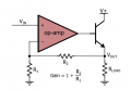
I attached an example I am trying to follow from:
https://www.allaboutcircuits.com/te...r-an-op-amp-output-for-higher-current-part-1/

Here is the pump I am using:
https://www.amazon.com/gp/product/B01IUVHB8E/ref=oh_aui_detailpage_o05_s00?ie=UTF8&psc=1

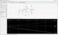
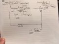
I have also attached a drawing of the circuit I am trying, as well as an image of the explicit example.

I have tested the pump and the op amp to make sure they are working properly, I also am using a 1Mohm and 1kohm resistor to try to maximize gain since the pump doesn't seem to be working.
I'm thinking I might be having an issue with supplying enough current to the pump, even though the pump only requires 80ma...but that's what I thought the transistor would solve. I used GND 1 and GND2 to represent that most of my circuit is attached to GND1, but the single supply I have to power the transistor is at a separate GND2, as I was unsure if this would cause problems since I have 2 power supplies attached to the same GND.

*EDIT*
the OP Amp and the transistor I'm showing here are the only ones I have available
 

Attachments

AnalogKid

Joined Aug 1, 2013
12,125
The two circuit power sources and the Arduino power source all *must* have a common ground, otherwise the base current from the opamp supply doesn't have a return path.

Are you sure the Arduino output is a varying DC voltage and not a PWM (pulse-width modulation) signal?

I suggest increasing R1 to 10 K (to reduce loading) and reducing R2 (the feedback series resistor) to 10 K. As the Arduino output varies from 0 v to 3 V, the voltage across the motor should vary from 0 V to 6 V. Not the full range you want, and the motor might not even start up. but it will confirm that the circuit is functioning properly with the motor attached. After that, the circuit can be adjusted.

What is the Arduino output voltage range?

ak
 

Thread Starter

quekwoambojish

Joined Jan 9, 2018
21
I'm awaiting for the arduino to arrive, so at the moment I am using a function generator with a DC offset to vary the signal from 3.3V to 5V. Both haven't been starting up the motor.

I varied the R1 and R2 to produce a ~12v signal when I attach an O-scope across where the pump normally would be, but when I attach the pump, I think it might be an issue that current isn't being supplied.

When I take the LF411 out of the picture (and it's gain setting resistors, and the dual power supply), and just use the transistor with a 1k resistor as indicated on
https://forum.arduino.cc/index.php?topic=443307.0
it works fine / :
 

AnalogKid

Joined Aug 1, 2013
12,125
That circuit is running the transistor more as a switch than as a linear amplifier or voltage to current converter. Note that the motor is connected to the collector, rather than to the emitter as in your circuit. Because you have a +14 V supply for the opamp, it should be possible for your circuit to work, but it needs more debugging.

ak
 

AnalogKid

Joined Aug 1, 2013
12,125
I think that if you replace M1 with a 150 ohm resistor, you will see that the circuit gain is incorrect. Also, Vs3 should have a max value of +5.0 V.

ak
 

Alec_t

Joined Sep 17, 2013
15,117
With a few circuit modifications you could ditch the ±14V supplies and run the opamp and pump from a single 12V supply.
 

ebeowulf17

Joined Aug 12, 2014
3,307
A sim seems to show it should work as a constant current source
drive for the motor. See atached.

The only issue with sim is not clear what the total spice model of Motor
looks like.

Regards, Dana.
Since the transistor is configured as an emitter follower, and the feedback is voltage at the emitter, wouldn't it be a voltage source, not a current source?

What happens if you plot voltage of the emitter/motor-positive node, then run the sim with two different sets of motor parameters? I wound think the voltage plot would stay the same, but the current plot would change as a function of motor specs.

Just brainstorming and trying to wrap my head around this one - I could definitely be misinterpreting this circuit!
 

ebeowulf17

Joined Aug 12, 2014
3,307
Its essentially this -


The current, thru load, is independent of Vcc.

Regards, Dana.
Isn't that only true when the load is Rc, and Rr is essentially a "sense" resistor used to measure current through the whole loop?

If the load is where Rr is, then the output is a regulated voltage, not a regulated current, right?

I agree it's independent of Vcc - I'm just not sure if it's a regulated voltage or a regulated current.
 

Thread Starter

quekwoambojish

Joined Jan 9, 2018
21
With a few circuit modifications you could ditch the ±14V supplies and run the opamp and pump from a single 12V supply.
I'm aware of this, but I avoided trying it out since I didn't want to bog myself down with potentially more variables I wasn't understanding.

I really should try doing what you guys did with that Spice diagram...Do you mind sharing your LF411 and 2N2 with me? (I use LTspice)
 

ebeowulf17

Joined Aug 12, 2014
3,307
Its essentially this -


The current, thru load, is independent of Vcc.

Regards, Dana.
I ran a few sims, albeit with generic parts, not the precise parts listed. Nevertheless, I'm pretty sure the fundamental behavior will be the same. I ran both sims with the input (Arduino signal) ramping from 0-5V. Both sims use a ".step param" command to run 3 times with different load resistance values.

In the first sim, I've used 1Meg and 1k, just like the thread starter's setup. You can see that this makes it behave more or less like a comparator, saturating the output high as soon as the signal moves above ground (83uV is where it tripped in simulation, so not much above ground!) When the opamp output saturates high, the NPN emitter follower tracks almost perfectly, roughly 0.7V below the opamp output, regardless of load resistance. With three different load resistances, the voltage remains (almost perfectly) constant, while the load current quadruples.
Plant-water-opamp_01.png


In the second sim, I wanted to actually see the ramp, so I switched the 1Meg to 1k. Now the opamp/NPN combo is a 2x amplifier - the 0-5VDC input ramp turns into a 0-10V output ramp. Again, this output voltage is essentially independent of load. Three different load values show the same voltages, and a quadrupling of current, just like the previous version.
Plant-water-opamp_02.png

Unless I'm way off base with this simulation, I'm pretty confident it's not behaving as a current source.
 

Attachments

ebeowulf17

Joined Aug 12, 2014
3,307
P.S. Here's the version configured as a current source - if the bottom resistor is a fixed value "sense" resistor and we move the load to the position of the top resistor, then we get a current source controlled by the Arduino signal.
Plant-water-opamp_03.png
 

Attachments

Top