HELP: 10.7Mhz FM Tx Circuit

Thread Starter

hamopp

Joined May 13, 2009
68
Hi All
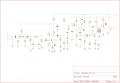
Having some probs with the Osc part of this circuit, the crystal should run at 10,7Mhz
but it runs at 10.7453Mhz, if i adjust L1 the lowest it will go is 10.7388Mhz.

I don't know the inductance of L1, but i put about 40 turns of 40swg wire on a 5mm dia
by 10mm long coil former with screen can and it's slug tuned.
I changed C59 from 5pF to 20pF and it brought it down to about 10.7368Mhz.

Now! i removed L1,C59,C10,D1,D2 and replaced with a trim cap 3-30pF so that Q02
would run as a standard crystal oscillator, but it would only go from about 10.7400 to 10.7650Mhz.

All frequency's are done without any audio input.

anyone able to help me out here ??

Regards
Hamopp
 

Attachments

bertus

Joined Apr 5, 2008
22,940
Hello,

Please do not use the 10.7 Mhz for a transmitter.
You will cause a lot of trouble using that frequency as it is the MF for most of the FM recievers.

Bertus
 

Thread Starter

hamopp

Joined May 13, 2009
68
Hi All

Bertus
Please do not use the 10.7 Mhz for a transmitter.
You will cause a lot of trouble using that frequency as it is the MF for most of the FM recievers.
This is NOT just a Transmitter, it is a FM MODULATOR AT 10.7Mhz, that is then mixed
with a local oscillator ie a DDS to give FM mode in a HF Transceiver, My HF Transceiver
just happens to have a Rx and Tx IF of 10.7Mhz, it could just as well be at 9Mhz!!

I do hold a UK Ham Radio licence

Regards
hamopp
 

Thread Starter

hamopp

Joined May 13, 2009
68
Hi
The above circuit is from a Yaesu FT-221, i was given the mic amp board
and i removed the 10.700Mhz crystal, vericap diode, diode D1 and the 10.700Mhz if transformer, but i broke the coil L1, which was on a 5mm dia x 10mm long former with slug, the wire is very thin (thinner than 40swg which i have).

L1 looked to be wound in a single layer, the length of the former, got a new former and i put on as many turns as i could with the 40swg (about 40 turns), this worked in a way, but i could not get the output freq down to 10.700Mhz by adjusting the slug.

So i changed the cap C59 (5pF) to 20pF and then i was able to get down to 10.700Mhz but the tuning of L1 is very hard to control, this i think is down to coil L1.

The vericap diode is a IS2687 and diode D1 is a IS1555.

All measurements are done without any audio input.

How can i work out how many turns and wire size are needed for L1 to be able to tune to 10.700Mhz and be stable ?.

Regards
hamopp
 

Thread Starter

hamopp

Joined May 13, 2009
68
Hi
Did you use the same coilholder?
Yes
Does this coilholder have a adjustable core?
Yes
Does tha manual say what coil is used?
No

The coil type is like a Toko 10k ver, 5 pins but with a single winding.

It look like there are still to less turns on the coil as the frequecny is still to high.
Can the wire dia be increased so that use less turns ?
as i don't think that i could wind a coil with thinner wire size :eek:

Regards
hamopp
 

Thread Starter

hamopp

Joined May 13, 2009
68
Hi
Sorry i can not measure the thickness of the old wire, as it was put in the trash.:mad:

I have sent an email to Yaesu in the uk, as i found the part number in the
service manual, but they are unable to help, they said that the radio is too
old, and they do not have any info on the coil, same for Yaesu in Japan.

Regards
hamopp
 

Thread Starter

hamopp

Joined May 13, 2009
68
Hi

Is it possible to wind the coil in double layer?
Well i did think about doing that, do you think it will work ?, good thing that i have a few of
these coil formers.
what kind of modification are you trying to do on the FT221?
I'am not doing any mods to a to a FT-221, i was given the mic amp board from this radio, so that i could use the parts to make a 10.7Mhz FM Modulator, so that i can get FM mode on my home-brew hf transceiver, which has a tx if of 10.700Mhz

Regards

hamopp
 

Thread Starter

hamopp

Joined May 13, 2009
68
Hi
I think that i need to make a coil with an inductance of about 28μH to
33μH

This will have to be wound on a 5mm dia x 10mm long former with a
adjustable core and screening can.

Can anyone help with what wire size and how many turns to wind on
the above former size to get about 28μH to 33μH.

Merry Xmas to all

hamopp
 

Thread Starter

hamopp

Joined May 13, 2009
68
Hi
Sorry but all this is above me :mad:

I did try a double layer winding with about 80 turns of 40 swg wire, but it
still did not tune the xtal on freq. lowest freq was 10.74022Mhz and went up to 10.7567Mhz (this was with a core that has a red mark on it)

I have just found my homebrew LC meter, that was still packed away from
when i moved house.

Read coil with red core and it goes from:
(top of former 24.48μH)
(middle of former 31.25μH)
(bottom of former 19.65μH)

Read coil with black core and it goes from:
(top of former 30.04μH)
(middle of former 41.12μH)
(bottom of former 21.54μH)

Read coil with no core (18.64μH)

Have not tried coil with black core in circuit yet!

All these readings are a bit jumpy with the core in the middle of the coil

Core with red mark (Al = 9.8) 1-10Mhz (have)
Core with black mark (Al = 7.2) 25-100Mhz (have)
Core with yellow mark (Al = 8.5) 10-50Mhz (not have)

Do you think that i will need to get a Core with yellow mark ?

Merry Xmas to all

hamopp
 

bertus

Joined Apr 5, 2008
22,940
Hello,

Do you have the datasheets of the coil formers?
This would probably give an indication on the possible coil values.

Bertus
 
Top