HC-05 Bluetooth Module not powering on in circuit

Thread Starter

Torran Dodd

Joined Nov 22, 2017
15
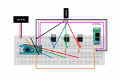
I am making an RGB LED lamp, which you control via Bluetooth using an app on your phone.
I had everything working on a PCB, everything soldered and good to go.
Originally, I was powering the circuit with a 2-way splitter cable (due to changes of plan) and, to tidy it up afterwards, I cut this cable before the split and soldered that, I was, however, surprised to see the green and white cables rather than red and black.
After soldering this, the Arduino I am using powered up fine, but the HC-05 module did not turn on at all, so I took it out and tested it and the Arduino on a breadboard using USB power and it worked fine, so I have nailed it down to a problem with power.
Any help with this?
 

Thread Starter

Torran Dodd

Joined Nov 22, 2017
15
OK, I will it over.
This image is for USB wiring colours.
This isn't a USB splitter though, it has a female DC power jack on one end, and splits it into two male DC power jacks.
Before the junction (the split) the wires inside are green and white (these are what I am now using and seem to be causing a problem) and after the junction the wires are red and black, I was using these before and it worked. Why does it not work anymore?

EDIT: The wires are red and black on the other end of the splitter too
This is a little confusing to follow.

This is a USB splutter that will take the 4 USB wires and split them into 2 data lines and 2 power lines.

https://www.aliexpress.com/item/USB...Y-Splitter-Hub-Adapter-Cable/32756141498.html

You are saying that you do not have that.

This is a 1 to 2 power splitter
https://www.bixpower.com/product-p/cnt-y25.htm

This looks like your picture - does it look like what you have?

If it is, then regardless of color, if the female has two inputs and each of the males have two connectors, they should duplicate the inputs. If you had tested the continuity before the operation, you would be able to determine what is actually connected..

Originally, I was powering the circuit with a 2-way splitter cable (due to changes of plan) and, to tidy it up afterwards, I cut this cable before the split and soldered that, I was, however, surprised to see the green and white cables rather than red and black.
After soldering this, the Arduino I am using powered up fine, but the HC-05 module did not turn on at all, so I took it out and tested it and the Arduino on a breadboard using USB power and it worked fine, so I have nailed it down to a problem with power.
Any help with this?
This is the part that is confusing. Are you saying that you are using the uncut portion of the cable? And, now it doesn't work whereas before you were using the cable uncut but only one of the male sides? Or are you saying that you are now using both the cable that has been cut and the portion of cable that was cut off (i.e., both male connectors)?

In any event, I am thinking that you should check the continuity from the female side to the male side that you are using. If there is continuity between the connectors as you think there should be, then look elsewhere...something got changed.
 

Thread Starter

Torran Dodd

Joined Nov 22, 2017
15
This is a little confusing to follow.

This is a USB splutter that will take the 4 USB wires and split them into 2 data lines and 2 power lines.

https://www.aliexpress.com/item/USB...Y-Splitter-Hub-Adapter-Cable/32756141498.html

You are saying that you do not have that.

This is a 1 to 2 power splitter
https://www.bixpower.com/product-p/cnt-y25.htm

This looks like your picture - does it look like what you have?

If it is, then regardless of color, if the female has two inputs and each of the males have two connectors, they should duplicate the inputs. If you had tested the continuity before the operation, you would be able to determine what is actually connected..


This is the part that is confusing. Are you saying that you are using the uncut portion of the cable? And, now it doesn't work whereas before you were using the cable uncut but only one of the male sides? Or are you saying that you are now using both the cable that has been cut and the portion of cable that was cut off (i.e., both male connectors)?

In any event, I am thinking that you should check the continuity from the female side to the male side that you are using. If there is continuity between the connectors as you think there should be, then look elsewhere...something got changed.
It is a power splitter, like the one you linked.
I was originally planning to use an Arduino Uno for this project, so I bought the splitter - one end could be chopped off and the wires stripped to power the circuit and one end could be left as it was to power the Uno.

I then switched to an Arduino Nano, which does not have a power jack, but I still used the splitter - as it was all I had. I chopped one end of it off (as pictured) and soldered the individual wires to the PCB - this powered the Arduino and the circuit and worked fine.
But this left me with a lot of spare cable, and an unused branch of the splitter, so I chopped the splitter before the junction and soldered that to my PCB - this did not work, for some reason. I was confused when I chopped before the junction in the splitter and one of the two wires was green and the other white, whereas after the junction one was red and one was black, as you'd expect.

I had eliminated all other possible faults in the circuit, re-soldered loads of joints, tested the individual components, tested the components together and I narrowed it down to a problem with the new cable used to deliver power - the BT module and Arduino worked fine when I tested them together on a breadboard, using a USB cable to power the Arduino.

I hope this makes more sense, I am awful at explaining things as it always makes sense to me but I know that's because I know first hand what I did xD Just say if you need any more info :)
 
That makes a little more sense.

I think you can and should quickly eliminate the power cable from contention as the problem. Even if you have to unsolder and remove the cable and use a meter to test the continuity. This is not too difficult, but something else that you have said may be notable.

You said "the BT module and Arduino worked fine when I tested them together on a breadboard, using a USB cable to power the Arduino."

How are you powering the Arduino Nano now? The old Arduino powered off a USB connector may have been providing more power than what you are providing to the NANO now - that is what I am getting at. Are you using a USB to Serial board? If so, that may be the problem - not enough power for the HC.
 

Thread Starter

Torran Dodd

Joined Nov 22, 2017
15
That makes a little more sense.

I think you can and should quickly eliminate the power cable from contention as the problem. Even if you have to unsolder and remove the cable and use a meter to test the continuity. This is not too difficult, but something else that you have said may be notable.

You said "the BT module and Arduino worked fine when I tested them together on a breadboard, using a USB cable to power the Arduino."

How are you powering the Arduino Nano now? The old Arduino powered off a USB connector may have been providing more power than what you are providing to the NANO now - that is what I am getting at. Are you using a USB to Serial board? If so, that may be the problem - not enough power for the HC.
The Arduino is powered by 12V 2A DC from the wall, using the cut splitter cable (the green and white bit) and the Arduino powers up - that works. However, it seems to not be outputting 5V to the BT module, as that is not lighting up. However, I know the 5V pin is working, as when I test the Arduino and BT module together on a breadboard, with the Arduino powered by a USB, they both work. This is what confuses me - the Ardunio has power, but isn't outputting it but I know it can.
 
I think you need to get hold of a multimeter. Then remove all connections except the power supply to the nano.

Verify that 12v is coming into the Vin pin on the nano .
Verify that the 5V pin on the nano has 5V.

Then add the HC-05 and check again and so on.

It's better to check than guess.
 
I am using an Arduino and a HC-05 Bluetooth module to make an RGB lamp controlled by an app on your phone.
It all works, however something has left me clueless.
I am very much so a newbie to electronics, this is my first ever project, however I still feel I have a good enough knowledge to know this shouldn't happen:

The HC-05 module is powered by the 5V output on the Arduino, which is then powered by 12V DC from the mains. This, however, does not power the BT module (for some reason) but the Arduino is powered. However, when I power the Arduino with USB - it powers them both up! Can someone please explain this to me, as surely when the Arduino is powered (as it is when powered only from the mains) it should power the BT module, but it only powers that with a USB attached...
Hi,

First off, it is probably better to stay with one thread since this is the same issue.

The bottom line is that you need to verify the voltages as I have explained in my last post. If you have already done that, please say so and say what they were at all points.

If you have not done so yet, please figure how to beg or borrow a meter so that you can do this. Just posting the problem in another thread is not the answer.

I know you are frustrated, but something is going on that you are not understanding. The way to get the problem solved is by isolating the components and checking them.

It works with an Arduino Uno powered by a USB port.

It doesn't work on an Arduino Nano powered by a supply that you believe is 12 V.

So, now you start checking the voltages - maybe you are over 12V and that shuts down the Nano's regulator. Maybe you are not getting 5 V out of the Nano to the BT. That is why I am advising you to check the voltages first. If they are ok, start adding the components and checking at each step.

The cure for frustration is a well executed plan.
 

Thread Starter

Torran Dodd

Joined Nov 22, 2017
15
Hi,

First off, it is probably better to stay with one thread since this is the same issue.

The bottom line is that you need to verify the voltages as I have explained in my last post. If you have already done that, please say so and say what they were at all points.

If you have not done so yet, please figure how to beg or borrow a meter so that you can do this. Just posting the problem in another thread is not the answer.

I know you are frustrated, but something is going on that you are not understanding. The way to get the problem solved is by isolating the components and checking them.

It works with an Arduino Uno powered by a USB port.

It doesn't work on an Arduino Nano powered by a supply that you believe is 12 V.

So, now you start checking the voltages - maybe you are over 12V and that shuts down the Nano's regulator. Maybe you are not getting 5 V out of the Nano to the BT. That is why I am advising you to check the voltages first. If they are ok, start adding the components and checking at each step.

The cure for frustration is a well executed plan.
I just tested it with a multimeter, the voltage into the Arduino is 12V, however with only this DC wall power it only outputs around 3.3V to the BT module, however with the USB plugged in too, it outputs around 4.5V to the BT module (which seems to be enough to turn it on).
 
I just tested it with a multimeter, the voltage into the Arduino is 12V, however with only this DC wall power it only outputs around 3.3V to the BT module, however with the USB plugged in too, it outputs around 4.5V to the BT module (which seems to be enough to turn it on).
Edited to add: Do not plug both the external 12V power supply into the Nano AND the USB power supply. For what I am advising below, use only the 12V supply. Also, do these tests with nothing else attached to the board except the 12V supply and the Nano.

Your result could be a clue.

There are many clones for the Nano and varieties of the HC05 to consider so, for the pictures below, make sure they represent what you have. For the HC05, take a look at this picture:

Pic from http://www.martyncurrey.com/hc-05-fc-114-and-hc-06-fc-114-first-look/

I see that Vcc for the HC-05 needs 3.6V-6V. So, 3.3V is not enough, but 4.5V that you get with the UNO and a USB is enough. That could be the reason that the HC05 does not boot. BUT there is more.

Take a look at a pic for the pinout of the Nano board:


You are putting 12V into Vin since you are not using the USB power.

There are two voltage output pins: a 3.3V and a 5V. If you are getting 3.3V to the HC05 AND you do not have the HC05 connected, you have a problem. It may be as simple as you need to move the connection to the 5V pin.

Measure these voltages without the HC05 connected. That is, measure them with only the Nano connected to the power supply.

Pin 27 is the 5V. When you connect 12V to Vin as you are doing, then this pin outputs 5V from the Nano's regulator. That is the pin that you want to use to power the HC05. (27 +5V Output or Input +5V output (from on-board regulator) or +5V (input from external power supply).

If you instead are using Pin 17, you will always get 3.3V and that is what you are reporting (17 -3V3 Output +3.3V output (from FTDI)).

see https://www.mouser.com/datasheet/2/595/Arduino_Nano3_0-220057.pdf

So, check those connections and let us know.
 
Last edited:

Thread Starter

Torran Dodd

Joined Nov 22, 2017
15
Edited to add: Do not plug both the external 12V power supply into the Nano AND the USB power supply. For what I am advising below, use only the 12V supply. Also, do these tests with nothing else attached to the board except the 12V supply and the Nano.

Your result could be a clue.

There are many clones for the Nano and varieties of the HC05 to consider so, for the pictures below, make sure they represent what you have. For the HC05, take a look at this picture:

Pic from http://www.martyncurrey.com/hc-05-fc-114-and-hc-06-fc-114-first-look/

I see that Vcc for the HC-05 needs 3.6V-6V. So, 3.3V is not enough, but 4.5V that you get with the UNO and a USB is enough. That could be the reason that the HC05 does not boot. BUT there is more.

Take a look at a pic for the pinout of the Nano board:


You are putting 12V into Vin since you are not using the USB power.

There are two voltage output pins: a 3.3V and a 5V. If you are getting 3.3V to the HC05 AND you do not have the HC05 connected, you have a problem. It may be as simple as you need to move the connection to the 5V pin.

Measure these voltages without the HC05 connected. That is, measure them with only the Nano connected to the power supply.

Pin 27 is the 5V. When you connect 12V to Vin as you are doing, then this pin outputs 5V from the Nano's regulator. That is the pin that you want to use to power the HC05. (27 +5V Output or Input +5V output (from on-board regulator) or +5V (input from external power supply).

If you instead are using Pin 17, you will always get 3.3V and that is what you are reporting (17 -3V3 Output +3.3V output (from FTDI)).

see https://www.mouser.com/datasheet/2/595/Arduino_Nano3_0-220057.pdf

So, check those connections and let us know.
The HC-05 is definitely connected to the 5V pin.
With just the Arduino hooked up to 12V power, no HC-05 module, the 5V pin reads 4.6V and the 3.3V pin reads 3.3V.
That is without the BT module, but then with it it is the same situation - 3.3V on the 5V pin and also 3.3V on the BT module pins...

This makes no sense to me :/ The pins output the correct voltage without the module, but with it output less..?

EDIT: Just to clarify, it works with a Nano with 12V + USB power too, that is what I am using - not an Uno. I apologise if that is what I originally put
At this point you have definitely made some progress. After double/triple checking that you are using the correct pins on the HC05, I would suggest that you reassemble the first setup using the UNO and the USB. I mean the one that did work with the HCO5. If it still works, then you can have some confidence that the HC05 is still ok.

If the HC05 works on the Arduino UNO with USB. I have to wonder whether the 5V out pin on the Nano can supply enough current to the HC05 - it should, but I don't know and it may not be able to. In htat case, you may want to give the HC05 its own power supply with a regulator off of the 12V supply and the GNDs connected. But you may not need to go there yet.

Also, if you can post a clear picture of the set up with the Nano (and UNO also) it might help because a fresh set of eyes might see something you have missed.

Edited to add: Are you saying that the Nano setup works when you only use the USB to power the Nano and the HC05 and with no led/transistors attached - only the USB connection (no 12V), the Nano and the HC05 - does that power up the HC05?
 
Top