Facebook
 Google
 GitHub
 Linkedin
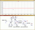
With reference to the below small datasheet:
https://www.limpkin.fr/public/HB100/HB100_Microwave_Sensor_Application_Note.pdf
I have created the two stage pre-amplifier and it appears to work great. I have paired it with matlab and generated script which logs the data. However, I have found that the IF output from the amplifier (10,000 times greater than input) is 1.6V and It fluctuates slightly depending on the doppler effect on the radar module.
Can anyone explain why the output is 1.6V? I imagine it would be much, much lower and would only fluctuate when movement was detected.
The reason being is I have just fried my 16bit ADC converter by inputting those very large values and amplifying it again by 8. OOPS!
Thanks for reading!
Regards
Rich