Facebook
 Google
 GitHub
 Linkedin
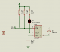
I brought a DS1307 chip incuding battery and crystal. I made the circuit in a breadboard and wired everything with arduino. It turns out that I can set the time, but the clock does not run at all. I have disconnected Vcc and the chip still holds time, but the clock does not run.
What is the problem?
I want to mention that I did not buy a module, beacuse I could build it myself.

What is the problem?
I want to mention that I did not buy a module, beacuse I could build it myself.