 Facebook
 Google
 GitHub
 Linkedin
Hola Keith
Here follows the answer I got from my friend (verbatim) and then what I hope is a passable translation:
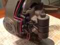
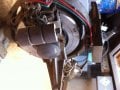
It seems to me a gyroscope but no from a gyrocompass (used in ships, he means) unless from a very old model, previous to WWII.
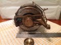
The small brass pipes are to lubricate the bearings.
The weights (counterweights?) provide an antagonic pair (force) to the handlers protruding (ahead?) as if a handler (arm) is bolted there.
Gyros (in gyrocompasses) were fed from the overhead and not from the side as this one.
You should ask him (that is, to you, Keith) how the power comes to the gyro if through the flexible or through some type of carbon (hope this is correct and makes sense).
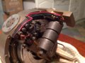
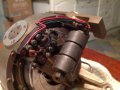
Yes, en tha last picture, where it is powered (?), there is a coil or a sensor.
Gyros had two coils (?) working as sensors to keep it upright. These coils fed the input of a servo type amplifier allowing the follower to follow the heading of the gyroscope or when the course was altered.
See what he says.
TEXT ENDS HERE.
Coloquial text is not always easy to translate. Sorry.
I recall seen the gyroscope of a Whitehead torpedo probably from around 1940-1950. Its gyroscope (air compressed propelled) had a, what I believe, much smaller toroid. But I could be wrong.
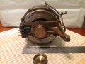
My suggestion: if you provide any further pictures, could you show it close to something allowing to appreciate size? Even a graduated ruler (centimeters) would help.
Here follows the answer I got from my friend (verbatim) and then what I hope is a passable translation:
TRANSLATIONAgustín , buenas tardes
Me parece que es un gyroscopo , pero no de un gyrocompass, salvo de un equipo muy viejo, anterior a las segunda guerra mundial.
Los tubitos de bronce que ves , son la lubricacion de los rulemanes.
Las pesas son las las que le dan un par antagonico a las manijas que salen hacia adelante como si algun brazo se atornillara alli.
Los gyros recibian alimentacion al gyroscopo de arriba y no de costado como este .
Habria que consultarle , como llega la alimentacion al gyroscopo ?? si por flexibles o algun tipo de carbon
Si en al foto ultima loque se ve alimentado , es una bobina o un sensor . Los gyros tenian dos bobinas que trabjaban de sensores para mantenerlo derecho. Estas bobinas alimentaban la entrada de un amplificador tipo servo y permitian que el seguidor siguiera ( sic ) al gyroscopo en su orientacion o en los cambios de rumbo.
Fijate que te dice
It seems to me a gyroscope but no from a gyrocompass (used in ships, he means) unless from a very old model, previous to WWII.
The small brass pipes are to lubricate the bearings.
The weights (counterweights?) provide an antagonic pair (force) to the handlers protruding (ahead?) as if a handler (arm) is bolted there.
Gyros (in gyrocompasses) were fed from the overhead and not from the side as this one.
You should ask him (that is, to you, Keith) how the power comes to the gyro if through the flexible or through some type of carbon (hope this is correct and makes sense).
Yes, en tha last picture, where it is powered (?), there is a coil or a sensor.
Gyros had two coils (?) working as sensors to keep it upright. These coils fed the input of a servo type amplifier allowing the follower to follow the heading of the gyroscope or when the course was altered.
See what he says.
TEXT ENDS HERE.
Coloquial text is not always easy to translate. Sorry.
I recall seen the gyroscope of a Whitehead torpedo probably from around 1940-1950. Its gyroscope (air compressed propelled) had a, what I believe, much smaller toroid. But I could be wrong.
My suggestion: if you provide any further pictures, could you show it close to something allowing to appreciate size? Even a graduated ruler (centimeters) would help.
Last edited:


 In the past I've been the user of the echosunders, radars and gyrcompasses he has repaired many times when calling our homeport. In the beginning, even a DF...


