 Facebook
 Google
 GitHub
 Linkedin
Hello,
I wonder if someone might be able to help me out with an issue I am having with a device I built. The device is for use with old Video Cameras which use the standard 10 pin Hirose EIAJ connector: https://www.amazon.com/Hirose-EIAJ-Circular-Male-Connector/dp/B00A0G5N1K
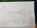
Basic I wanted to a solution to both power and record video from these cameras digitally. So I built a device that gives a 12v power supply from three 26550 batteries, and a PCB with an arduino and a reed relay that deals with the logic of triggering start and stop recording on the DVR device. The DVR device is external, I had hoped to make it internal using a drone fpv recorder but the sound on those devices is very poor. So instead I build an 8 pin mini din breakout socket on the device that can interface with a modified external recorder, e.g. https://www.amazon.co.uk/DIGITNOW-Capture-Digital-Converter-Records/dp/B01DJCDYKI (I added an 8 pin mini din port to this device so I could use a single cable to connect everything).
The breakout cable carries video/audio and the record trigger to the DVR. I'd also like it to carry 5v power to the DVR so I don't have to rely on its internal battery. All is working well, except the power. If I connect up this wire the device is powered from it but there is interference to the audio signal, and on a different DVR, to the video signal. I suspect a ground loop issue somewhere, or perhaps it's just interference from the power wire through the 8 pin din. I'm not sure. But certainly if I use a different power supply to the DVR I don't get the issue. Attached is a sketch of the setup (please excuse the amateur nature of it)
I had one pin for the common ground connection with my device. I tried breaking this up so the AV ground and power ground are separate pins but as they are common in both camera and DVR it didn't make much difference. I've heard of ground isolators and such like, but not sure how they would fit in the setup I have. Would appreciate any advice. One thing I would mention is that while there is no resistance between the av ground and power ground on the DVR in idle state, a small resistance (around 20-40 ohms) does occur when the device is powered on by a separate power source. Not sure where this is from and, as you'll gather, I'm a bit of a noob on these matters.
Please, if anyone can suggest anything to help eliminate the problem I would really appreciate any insight, and I'm obviously rather restricted by the fact that two of the three devices are not easily modifyable.
Thanks very much.
I wonder if someone might be able to help me out with an issue I am having with a device I built. The device is for use with old Video Cameras which use the standard 10 pin Hirose EIAJ connector: https://www.amazon.com/Hirose-EIAJ-Circular-Male-Connector/dp/B00A0G5N1K
Basic I wanted to a solution to both power and record video from these cameras digitally. So I built a device that gives a 12v power supply from three 26550 batteries, and a PCB with an arduino and a reed relay that deals with the logic of triggering start and stop recording on the DVR device. The DVR device is external, I had hoped to make it internal using a drone fpv recorder but the sound on those devices is very poor. So instead I build an 8 pin mini din breakout socket on the device that can interface with a modified external recorder, e.g. https://www.amazon.co.uk/DIGITNOW-Capture-Digital-Converter-Records/dp/B01DJCDYKI (I added an 8 pin mini din port to this device so I could use a single cable to connect everything).
The breakout cable carries video/audio and the record trigger to the DVR. I'd also like it to carry 5v power to the DVR so I don't have to rely on its internal battery. All is working well, except the power. If I connect up this wire the device is powered from it but there is interference to the audio signal, and on a different DVR, to the video signal. I suspect a ground loop issue somewhere, or perhaps it's just interference from the power wire through the 8 pin din. I'm not sure. But certainly if I use a different power supply to the DVR I don't get the issue. Attached is a sketch of the setup (please excuse the amateur nature of it)
I had one pin for the common ground connection with my device. I tried breaking this up so the AV ground and power ground are separate pins but as they are common in both camera and DVR it didn't make much difference. I've heard of ground isolators and such like, but not sure how they would fit in the setup I have. Would appreciate any advice. One thing I would mention is that while there is no resistance between the av ground and power ground on the DVR in idle state, a small resistance (around 20-40 ohms) does occur when the device is powered on by a separate power source. Not sure where this is from and, as you'll gather, I'm a bit of a noob on these matters.
Please, if anyone can suggest anything to help eliminate the problem I would really appreciate any insight, and I'm obviously rather restricted by the fact that two of the three devices are not easily modifyable.
Thanks very much.
Attachments
-
 3 MB Views: 5


