Grounding and signal distribution across multiple power supplies

Thread Starter

AleMonti

Joined Aug 11, 2024
37
Hi everyone,

I'm planning the wiring for a large addressable LED setup powered across several separate 5V power supplies (around 1500W total). The power supplies are within 4 meters from each other and share the same AC mains feed with their metal chassis grounded to earth, but their DC outputs are currently separate.

I'm trying to figure out the cleanest, safest way to distribute data from a single central controller to all strips without running into ground loops or signal integrity issues. I'd really appreciate some feedback on the trade-offs between the following approaches or other guidance into alternatives I didn't consider.

Level shifters (data + ground)
Given the relatively short distance, the simplest route is driving 5V TTL data alongside a ground wire over cat5 to each strip, however I have a few concerns. Running a ground wire from every strip back to the controller ties all the different PSU ground rails together through thin ethernet conductors. If there is any voltage drop or ground bounce between the supplies under load, return currents might try to route through those signal ground wires. If a main DC ground connection to a strip were to work loose or fail, wouldn't the entire load current for that zone try to return through the thin ethernet ground wire back to another PSU and cause a fire hazard?

Differential signaling (RS-422)
To keep the signal completely independent of heavy return currents, I considered using differential RS-422 drivers like so:
The controller board outputs differential pairs over standard cat5 cables and a single external reference wire carries the controller digital ground (CTRL_GND) alongside the ethernet bundle. Passive boards then take each RJ45 cable and the shared ⁠CTRL_GND⁠ line and split them into individual 3 wire channels (differential A, differential B, and ⁠CTRL_GND⁠). At each strip input is a small board powered locally by that strip's power supply (⁠+5V⁠ and ⁠LOCAL_GND⁠). On it, the incoming ⁠CTRL_GND⁠ line connects to the strip's ⁠LOCAL_GND⁠ through a 100Ω series resistor to establish a shared reference without creating a hard DC short between supplies, and an RS-422 receiver IC decodes the differential pair into 5V TTL directly into the first pixel.


Is the RS-422 + 100Ω ground reference resistor approach a good solution for handling floating supplies or am I overcomplicating this? Would simply bonding all the PSU DC grounds together with heavy wire and using standard level shifters be reliable enough?

Or generally, what is the standard/best practice for this kind of multi PSU setup?


Thanks in advance for any insights or suggestions!
 

MisterBill2

Joined Jan 23, 2018
28,039
The way to avoid the problems is to arange the wiring so that no signal current flows thru any wire that also carries the power current. (Which is the definition of a ground loop.

There is all of the information missing regarding the required data connections, with only a mention of RS422 as a possible option, and the statement: "The controller board outputs differential pairs over standard cat5 cables and a single external reference wire carries the controller digital ground (CTRL_GND)".

With no detailed information about the actual digital data scheme, the very best you can expect is educated guesses.

Let us know about the actual controller data connection scheme: Is it an isolated differential pair, or is it a ground referenced pair? AND ALSO: the data connection on the LED strips?? IS it RS-422? or similar?? Is it isolated, or differential with a balanced "ground" conection??
 

Thread Starter

AleMonti

Joined Aug 11, 2024
37
Thanks for the response, and apologies for leaving out those details in my original post. To clarify:

The system uses a 3.3V microcontroller generating 32 parallel data channels to drive standard addressable LED strips using the WS2811 protocol. The strips require a single ended 5V 800 kHz single wire NRZ data signal with CMOS logic levels (VIH ~3.5V, VIL ~1.5V), referenced to their local supply ground.

Because the installation draws substantial current across roughly 1500W of distributed 5V power supplies, my primary concerns are signal corruption from ground bounce and the fire hazard of unintended DC fault return paths.

The first option I thought of is what is usually done on small setups where a single PSU powers everything: placing 5V level shifters directly at the central controller and running a single ended 5V data line alongside a signal ground wire to each strip. My hesitation is that running 32 signal ground lines ties all separate PSU negative rails back together at the controller board through thin ethernet conductors. Dynamic load shifts could induce ground bounce that shifts the signal reference outside the CMOS logic window. Worse, if a power ground connection fails on an active strip, that thin signal ground wire becomes an accidental return path for high current and could overheat or catch fire.

The second option is using non isolated RS-422 differential transmission purely as an intermediate transport layer. The 3.3V MCU feeds 32 differential transmitters referenced to the controller ground. At each strip input, a small receiver board decodes the A and B signals back into single ended 5V CMOS data right before the first pixel. To absorb ground bounce and keep common mode voltage within the RS-422 receiver threshold without creating a hard short between separate supplies, the controller ground line ties to the local strip ground through a 100Ω series resistor at each receiver board.

I am not fixed on either design and would appreciate feedback on whether these assumptions are correct.
 

Thread Starter

AleMonti

Joined Aug 11, 2024
37
Maybe, but copper is expensive these days, and glass fibre isn't.
Fair, but in this setup 32 channels only take 8 cat5 runs (under 100m total) since each cable carries 4 differential pairs. The cable cost is negligible, so copper definitely wins on economics here, especially once you price out the transceivers.
Would definitely be fun trying to drive an LED strip from 10km away over single-mode fiber, though!
 

Ian0

Joined Aug 7, 2020
13,228
Fair, but in this setup 32 channels only take 8 cat5 runs (under 100m total) since each cable carries 4 differential pairs. The cable cost is negligible, so copper definitely wins on economics here, especially once you price out the transceivers.
Would definitely be fun trying to drive an LED strip from 10km away over single-mode fiber, though!
Use RS485 - just connect your WS2811 signal to an RS485 transmitter, and an RS485 receiver to your LEDs.
If your grounding is really dubious, then there are isolated RS485 transceivers., but some of the fancy ones with guaranteed overvoltage are getting as pricey as the fibreoptic transceivers!
You can get Quad RS485 transmitters, and single receivers.
 

Thread Starter

AleMonti

Joined Aug 11, 2024
37
Use RS485 - just connect your WS2811 signal to an RS485 transmitter, and an RS485 receiver to your LEDs.
If your grounding is really dubious, then there are isolated RS485 transceivers., but some of the fancy ones with guaranteed overvoltage are getting as pricey as the fibreoptic transceivers!
You can get Quad RS485 transmitters, and single receivers.
That aligns with what I had in mind in approach 2, though all in one isolated transceivers or isolated DC-DC supplies across 32 channels are definitely too expensive for this build.

I was planning to use eight AM26C31IDR quad line drivers on the 32-channel controller board and cheap GM75176E transceivers as dedicated receivers at each strip, with a 100Ω series resistor between the controller ground and the local strip ground at each receiver board.

If we go the differential route, how do you recommend connecting the grounds across the separate supplies? Is the series resistor approach valid?
 

Ian0

Joined Aug 7, 2020
13,228
You'll need it terminated at both ends if you going to get 1.5Mbit/second down it!
First thing I looked at on your datasheet was the supply current. <1mA is good. Some of them (like the good old SN75176) need 50mA!
100Ω to earth is as good as anything. Whether you'll need extra input protection (TVS diode) is debatable. Although it will withstand 15kV pulses, a continuous 24V will probably kill it.
RS485 will go a mile at low data rates and the chance of the earths at both ends both being the same voltage seems unlikely.
 
OK, I am revisiting this question a few days later!
The working solution will be isolation! Separate wires for the five volts power and the digital signals. Each 5 volt power supply connected to a group of LED modules thru properly rated wire pairs. A separate conductor tying the common sides together .
The 32 digital control signals from the "32 channel controller" will be a much thinner gage of wire pairs for each channel.
What is totally unclear is if there is any connection between the power feed terminals and the control signal terminals.
 

Thread Starter

AleMonti

Joined Aug 11, 2024
37
You'll need it terminated at both ends if you going to get 1.5Mbit/second down it!
First thing I looked at on your datasheet was the supply current. <1mA is good. Some of them (like the good old SN75176) need 50mA!
100Ω to earth is as good as anything. Whether you'll need extra input protection (TVS diode) is debatable. Although it will withstand 15kV pulses, a continuous 24V will probably kill it.
RS485 will go a mile at low data rates and the chance of the earths at both ends both being the same voltage seems unlikely.
Thanks for the feedback!

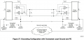
I came across this TI Application Report, and Section 4.5.2 (Figure 27) illustrates the exact topology I we are evaluating (what I called approach 2 before):
In many cases, local ground and PE are connected by wire, chassis, or leakage for many reasons, such as lowest cost or simplest power supply design. Thus, if a high-voltage potential difference exists between remote grounds, especially during transients, then current flows through the remote ground because a ground loop does exist. If the ground loop has no resistance , then the ground current is large and creates some problems. For this reason, the RS-485 standard recommends adding some resistance between logic and chassis ground to avoid excess ground-loop currents (Figure 27).
fig27.png

Regarding termination, since each of the 32 channels is a point to point link, standard practice from Section 4.2 (Figure 19) is placing a 100Ω parallel termination resistor across A and B only at the receiver end. Placing termination at both ends is required for bidirectional multipoint buses where transmission originates from multiple points, which isn't the case here.
As for the TVS, I agree it's probably not strictly necessary, but I'll add footprints on the receiver boards just in case.


OK, I am revisiting this question a few days later!
The working solution will be isolation! Separate wires for the five volts power and the digital signals. Each 5 volt power supply connected to a group of LED modules thru properly rated wire pairs. A separate conductor tying the common sides together .
The 32 digital control signals from the "32 channel controller" will be a much thinner gage of wire pairs for each channel.
What is totally unclear is if there is any connection between the power feed terminals and the control signal terminals.
I'm currently pursuing what in posts #1 and #3 I called approach 2. Here is how the power routing is structured:

At the central controller:
The controller runs off its own power supply and outputs 32 differential pairs (A and B) plus its own digital ground (CTRL_GND) over the Cat5 cables.

At the LED Strips:
Each strip cluster has a dedicated receiver board right at the strip power injection point. The receiver board is powered directly by that strip's local power supply (+5V_LOCAL and GND_LOCAL). The receiver IC outputs single ended 5V data directly into the strip's data in pin, referenced to GND_LOCAL. The incoming CTRL_GND reference wire from the controller connects to GND_LOCAL only through a 100Ω series resistor on the board.

The DC power outputs of the different 5V power supplies are completely separate, but their metal chassis (connected to PE earth) and AC power share the same outlet. Each 100Ω resistor bridges the signal ground to the corresponding local power ground to provide a common mode reference without creating a low impedance DC path between supplies.
 

BobTPH

Joined Jun 5, 2013
11,617
Using 3.3V signals to control a 5V WS2812 strip might look like it works, but it is marginal at best. I know this from experience. I had 8 such system and they failed intermittently. If I remember correctly, the logic high level is 80% of Vdd, which is 4V. If that is correct, the signal from a 3.3V micro is out of spec.

The ultimate solution was to use a high speed CMOS line driver which had a lower input threshold and output good 5V signal. This also helps with long signal lines.

Edit: Looked up the actual logic thresholds. It is actually 70%, so 3.5V. Still out if spec.
 
Last edited:

Thread Starter

AleMonti

Joined Aug 11, 2024
37
Using 3.3V signals to control a 5V WS2812 strip might look like it works, but it is marginal at best. I know this from experience. I had 8 such system and they failed intermittently. If I remember correctly, the logic high level is 80% of Vdd, which is 4V. If that is correct, the signal from a 3.3V micro is out of spec.

The ultimate solution was to use a high speed CMOS line driver which had a lower input threshold and output good 5V signal. This also helps with long signal lines.
Sure that's correct, but level shifting was never the issue here. As stated multiple times in this thread, the 3.3V signals never leave the controller board. The issue being discussed is managing ground loops and common mode offsets across the power supplies...
 

BobTPH

Joined Jun 5, 2013
11,617
Sure that's correct, but level shifting was never the issue here. As stated multiple times in this thread, the 3.3V signals never leave the controller board. The issue being discussed is managing ground loops and common mode offsets across the power supplies...
It’s just a friendly warning that any solution must respect the 3.5V logic threshold. I was not trying the solve his issue.
 
Top