Facebook
 Google
 GitHub
 Linkedin
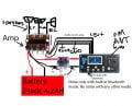
I have a little amplifier and preamp board which share the same 24v dc power supplied from a battery. Power is being converted to 12vdc through a buck converter. Everything works, but of course, I get a ground loop when I set the preamp to bluetooth especially when it connects to my phone it can be heard. I did use both with separate power sources, and the noise was gone. Separate power sources is not really an option. I have seen videos on different methods of fixing this issue, but not one that pertains to the setup I have. How can I go about eliminating the noise caused by the groundloop? Any assistance is appreciated.
Ground loop problem
- Thread starter Maverick923
- Start date


")