Facebook
 Google
 GitHub
 Linkedin
millwood
- Joined Dec 31, 1969
- 0
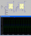
and that made them NOT identical to each other, and NOT comparable to the circuit we discussed.The two 555 timer circuits are identical, except that U1 has an LED load on it's output.
the output pin in the 555 has its output impedance: the data sheet gives you some hint about how big it is but for precision timing, you shouldn't be driving more than 1k load.
in our design, we are delivering 44ma in one direction, and 37ma in another direction.
in your design, one 555 is pulling about 40ma, and the other 555 is seeing no DC load. Hello?!
the load is affecting the output voltage on the output pin, thus the charging up / discharging of the rc timing network.
try to have your other 555 deliver a comparable current and then compare the two.
again, the "voltage" from your load means nothing. What does is the current.
simulation doesn't mean anything if you don't know what you are simulating.

") .
.