Facebook
 Google
 GitHub
 Linkedin
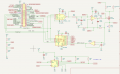
I have built the attached circuit on a breadboard. It is basically a Pi Zero W controlling a DAC/op-amp/MOSFET current source with two different current measuring circuits. One cicuit measures the current through the low side R223, 0.19R 2 watt resistor (measured value) and a MCP3008 ADC. The other circuit measures the same current on the high side using an INA260. The load at this point is just a car light bulb (~8.9R). What I am really after is measuring the current through rocket igniters (~0.4R), by replacing the bulb with the igniter. I am using the light bulb as a proxy so I don't have to burn up a bunch of igniters, and to test the circuitry.
My preliminary results (all mA) with a 1 msec pause before reading the values:
I can't find any oscillations in the circuit. I am interested in suggestions to help get these measurements closer in agreement, or, is this the best that can be done with the parts I have? Which measurement method is closer to the real current, whatever that is?
My preliminary results (all mA) with a 1 msec pause before reading the values:
| Programmed Current | INA260 | R223/ADC |
| 200 | 98.75 | 16.96 |
| 300 | 178.75 | 67.85 |
| 300 | 180.0 | 67.85 |
| 500 | 342.5 | 169.61 |
I can't find any oscillations in the circuit. I am interested in suggestions to help get these measurements closer in agreement, or, is this the best that can be done with the parts I have? Which measurement method is closer to the real current, whatever that is?
Attachments
-
280.7 KB Views: 26
-
1.2 MB Views: 14
Last edited:
")