
Hi
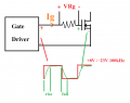
Please refer to the attached circuit. It shows my gate driver (+8V/-23V, 100kHz output). I would like to know how much average current it supplies the MOSFET's gate during the rise/fall time of Vgs. (Not the periodic average, because it's 0 A obviously). I have no current probe with me because it's f_ _ king expensive...
So, here is my plan to measure. (Let's do it for the rise time)
1. Hook the oscilloscope's probe across Vgs.
2. Calculate dVgs/dt at each point during the rise time. Let's say we got dVgs/dt@t1...... dVgs/dt@t10
3. Calculate the equivalent gate capacitance from the total gate charge curve of my MOSFET: K2837

Qg(rise time) = Qg(-23V to 0V) + Qg(0V to 8V)
Ceq = Qg(rise time) / [8 - (-23)]
4. Calculate Ig ----> Ig@t1 = Ceq(dVgs/dt@t1) ... Ig@t10 = Ceq(dVgs/dt@t10)
5. Ig average = (Ig@t1 + Ig@t2 + ... + Ig@t10)/10
I would like to know if hooking the oscilloscope across Vgs would affect its operation or not?
Also, is there any key point that I forgot according to my plan?
BlackMelon
Please refer to the attached circuit. It shows my gate driver (+8V/-23V, 100kHz output). I would like to know how much average current it supplies the MOSFET's gate during the rise/fall time of Vgs. (Not the periodic average, because it's 0 A obviously). I have no current probe with me because it's f_ _ king expensive...
So, here is my plan to measure. (Let's do it for the rise time)
1. Hook the oscilloscope's probe across Vgs.
2. Calculate dVgs/dt at each point during the rise time. Let's say we got dVgs/dt@t1...... dVgs/dt@t10
3. Calculate the equivalent gate capacitance from the total gate charge curve of my MOSFET: K2837
Qg(rise time) = Qg(-23V to 0V) + Qg(0V to 8V)
Ceq = Qg(rise time) / [8 - (-23)]
4. Calculate Ig ----> Ig@t1 = Ceq(dVgs/dt@t1) ... Ig@t10 = Ceq(dVgs/dt@t10)
5. Ig average = (Ig@t1 + Ig@t2 + ... + Ig@t10)/10
I would like to know if hooking the oscilloscope across Vgs would affect its operation or not?
Also, is there any key point that I forgot according to my plan?
BlackMelon
Attachments
-
 21.2 KB Views: 11
")


