Frequency detector using OP-AMP

Thread Starter

Marcel DaJanchar

Joined Sep 9, 2015
32
Hello everyone!

I want to make circuit which measures frequency of a given square wave and outputs HIGH when frequency is in pre-set range (230-250Hz) and LOW otherwise. This project is on budget, so I want to make it without microcontroller. Is it possible to use OP-AMPs to create one hell-of-a steep notch filter followed by schmitt trigger to filter out only a thin range of frequencies (20Hz range)? The signal measured would fluctate from 10 to 300Hz.

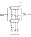
I tried attached schematics, but the response of the filter was still too big. Is it possible to create more than -6dB attenuation per octave with following circuit?

Thanks for all the answers
 

Attachments

wayneh

Joined Sep 9, 2010
18,090
Depending on what you actually need, I'd start with an app for tuning a guitar. The B string (second thinest) on a guitar is normally tuned to 246.9Hz. Some of the many apps available will show the frequency it measures as well how far it is from the target. When the string frequency falls into a narrow range, the app makes a tone and indicates that the string is properly tuned.

I know this may not be useful for your specific application, but maybe some of the ideas used in musical tuning would apply. I don't know a lot about the area but I think you're going to need an accurate reference frequency. Guitar tuners usually use a quartz crystal, for instance.
 

Norfindel

Joined Mar 6, 2008
326
But a square wave is full of harmonics, so in this case harmonics of the signal will likely get pass the filter.
There are some small, cheap MCUs out there. As you're dealing with square waves, it seems ideal to use an MCU. You could make an easy program to measure the amount of cycles over time, and the result will be as selective as it gets. Specially if the MCU has a timer that can count from an external signal.
 
Last edited:

OBW0549

Joined Mar 2, 2015
3,566
Instead of messing around with op amps, why not try an NE567 Tone Decoder chip? It appears to do what you want, with a minimum of external components.

From the description:

The LM567 and LM567C are general purpose tone decoders designed to provide a saturated transistor switch to ground when an input signal is present within the passband. The circuit consists of an I and Q detector driven by a voltage controlled oscillator which determines the center frequency of the decoder. External components are used to independently set center frequency, bandwidth and output delay.
 

BR-549

Joined Sep 22, 2013
4,928
Digital electronics has almost done away with a "budget". How does 43 cents sound?

https://www.digikey.com/product-detail/en/ATTINY4-TSHR/ATTINY4-TSHRCT-ND/2477315

http://ww1.microchip.com/downloads/en/DeviceDoc/ATtiny4-5-9-10-Data-Sheet-DS40002060A.pdf

One has to learn a little geek. Understanding a device like this, will open a new and coming future to you.

It cost nothing to program and your task is relatively simple. Hundreds of tutorials on web.


Edit: Using a micro controller to frequency filter your square waves......would be absolute(relatively), and allow an adjustable bandwidth.
 
Last edited:

iONic

Joined Nov 16, 2007
1,662
I agree with OBW0549, the LM567 was made for this. But only if you do not know how to program uC. If you can program a uC, then BR-549's solution would be a very slick solution.
 

crutschow

Joined Mar 14, 2008
38,333
the LM567 was made for this. But only if you do not know how to program uC.
??
The LM567 does not need any programming or a μC for operation.
It outputs a logic signal when it detects a frequency within the set range which is determined by value of R and C elements at the control inputs.
 

Sensacell

Joined Jun 19, 2012
3,770
The LM567 Tone decoder chip is a great option.

Another idea that might work if you don't need / want fast response would be a charge pump F-to-V converter, driving a window comparitor.
 

Thread Starter

Marcel DaJanchar

Joined Sep 9, 2015
32
Wow thanks for so many ideas! I was hoping to make this project without MCU because I didn't know about ATTINY being so cheap. But now I see that this is nonsense. I will order few of them and play around. Is the internal oscillator of the ATTINY accurate enough to calculate time between two interrupts for such low frequencies?

On the other hand, I didn't know about LM567. It looks like they can do all I need. Thanks.
 

BR-549

Joined Sep 22, 2013
4,928
Glad to hear that you will look into it. You might want to check out the different learning and programming boards that the mcu companies make. Many can be found for 5-10 bucks. Top of the line equipment can be had for 20 bucks.

These would be much quicker and easier to learn on......than the chip I posted. The chip I posted was for your function, not necessarily to learn on.

I would recommend you start out with an 8 bit chip. It will seem to complicated at first, but stick with it. You'll like it.

We have top programmers and hardware people on this site.
 

Thread Starter

Marcel DaJanchar

Joined Sep 9, 2015
32
@BR-549 Thanks for encouraging words! I have some experience with common basic mcu programming (arduino, stm32, esp8266...) so that shouldn't be a problem. I still need to learn some basic things (internal oscilators, fuses...) but that wouldn't matter for this project so much.

I will also try to make this circuit with Tone decoder LM567. I have one question here.. I am looking in the typical application in the datasheet and saw capacitor on the input of the chip. Will this capacitor change my square wave tone? Don't mind the application itself (it is some random application), I just need info about capacitor. Thanks!

.
 

Attachments

OBW0549

Joined Mar 2, 2015
3,566
I will also try to make this circuit with Tone decoder LM567. I have one question here.. I am looking in the typical application in the datasheet and saw capacitor on the input of the chip. Will this capacitor change my square wave tone? Don't mind the application itself (it is some random application), I just need info about capacitor.
The capacitor will have some effect on the waveshape, but it won't affect the frequency. The input resistance of the NE567 is about 20 kΩ, so I'd think 1 μF or even 100 nF would suffice for the capacitor.
 
Top