Since you know the input voltage and the battery voltage it should be fairly simple to determine when the diode conducts (is forward biased) and when it is not.
Post you best attempt at doing that, and we will help.
I have to agree with the previous post here you have to show us at least one attempt at how you would do this yourself and that helps us to help you do it the way you are most familiar with. I will give a couple little hints though.
First, you are lucky this is a battery charging circuit and now a half wave or full wave rectifier circuit as those types are much harder ot solve.
One hint is that with most circuits that have diodes that switch on and off, you have to solve for not only the voltage and current but also the time the diode is on an the time it is off. Solving for those times will provide the answer. The diode specs and the battery specs will help you understand how to solve for the voltage and current and the time fits right in with that.
Give it a shot and post your results here and im sure several members would be happy to help.
Since you know the input voltage and the battery voltage it should be fairly simple to determine when the diode conducts (is forward biased) and when it is not.
Post you best attempt at doing that, and we will help.
Hi there, I didn’t mean to like ask the answer for the question. I’m so sorry if it seems that way. I just wanted advice on how to do this questions. I wanted to understand on how to solve this with explanations. Again, I’m very sorry I didn’t mean to ask for answers to the question but I have been going through the internet looking for ways to solve this questions and haven’t gotten one yet. I’m fairly new to this course I’m studying so I’m a bit lost.
I have to agree with the previous post here you have to show us at least one attempt at how you would do this yourself and that helps us to help you do it the way you are most familiar with. I will give a couple little hints though.
First, you are lucky this is a battery charging circuit and now a half wave or full wave rectifier circuit as those types are much harder ot solve.
One hint is that with most circuits that have diodes that switch on and off, you have to solve for not only the voltage and current but also the time the diode is on an the time it is off. Solving for those times will provide the answer. The diode specs and the battery specs will help you understand how to solve for the voltage and current and the time fits right in with that.
Give it a shot and post your results here and im sure several members would be happy to help.
The continuation of my attempt at it, so I got like about 49.91% and this would have to be diode on “on state” right? To like obtain the percentage cycle of diode on “off state” I would just have to take a 100% and minus 49.91% right?
I have to agree with the previous post here you have to show us at least one attempt at how you would do this yourself and that helps us to help you do it the way you are most familiar with. I will give a couple little hints though.
First, you are lucky this is a battery charging circuit and now a half wave or full wave rectifier circuit as those types are much harder ot solve.
One hint is that with most circuits that have diodes that switch on and off, you have to solve for not only the voltage and current but also the time the diode is on an the time it is off. Solving for those times will provide the answer. The diode specs and the battery specs will help you understand how to solve for the voltage and current and the time fits right in with that.
Give it a shot and post your results here and im sure several members would be happy to help.
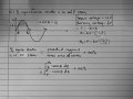
My another attempt at it, this time I plus the potential barrier with the battery voltage which is 0.7+3=3.7
If the input voltage is less than 3.7V then the diode becomes reverse biased isn’t it? And therefore making it and open-circuit which means it’s in “off state”, right?
After this, by integrating the graph of the “on state” and dividing the area of the total graph and multiplying by 100 I would get the percentage of “on state”
Later on I could figure out the percentage of diode in “off state” by 100-(percentage of diode in “on state”)
Pls correct me if I’m wrong
After this, by integrating the graph of the “on state” and dividing the area of the total graph and multiplying by 100 I would get the percentage of “on state”
Oh okay, I will look into that too.
But so far about my latest calculation are correct? I’m not sure about the calculations because I’m afraid I’m missing something.
View attachment 267258My another attempt at it, this time I plus the potential barrier with the battery voltage which is 0.7+3=3.7
If the input voltage is less than 3.7V then the diode becomes reverse biased isn’t it? And therefore making it and open-circuit which means it’s in “off state”, right?
After this, by integrating the graph of the “on state” and dividing the area of the total graph and multiplying by 100 I would get the percentage of “on state”
Later on I could figure out the percentage of diode in “off state” by 100-(percentage of diode in “on state”)
Pls correct me if I’m wrong
It looks like you are on the right track just a couple notes here.
First, if you are going to calculate the area of the shaded part of your drawing, you cant just integrate from angle 1 to angle 2 you got from using the inverse sine functions. That's because the area UNDER that shaded area is NOT included in the area of the shaded area. So really you'd have to subtract the area under the shaded area section from the total area from angle 1 to angle 2.
But the more important point is why would you want to integrate. It appears that you wanted to calculate some sort of power ratio, but the question is more about duty cycle. For example, if you had a total pulse time of 10 seconds and the 'on' time was 2 seconds that would mean the 'off' time would be 8 seconds, and so the percent 'on' time would be 2/10 and the percent off time would simply be 8/10. See how that works? It's really quite simple.
Now even though this is a sine wave the time measurement is still along the x axis which we can take as the angle or the time axis if we have the choice of frequency. So we can either compare angles or compare times.
See if that helps.
BTW you did very well in thinking this out based on your diagram and your initial calculations of the two angles. You just have to understand what to use for obtaining the ratios. When you look for something related to just duty cycle, you only have to compare time values or angle values. If you had to look for some sort of power ratio then you would need to integrate at some point most likely.
I've included a rotated version of your image and i think you did a good job of drawing this out, very neat and easy to understand.
Thank you very much for the further explanations about the graph, so in this case if I can figure the time when diode is in “on state” and the total time taken for one cycle, I can already find its ratio. I see that now, I realised why crutschow told me to look at the time diode is in “on state”. It’s much simpler than integrating, I realised that now.
I want to thank you guys for your feedback and guidance towards solving this problem. Have a great day ahead.
Oh i and want to make it clear that it's not just that integrating is a little harder to do, it's that integrating will not provide for the correct ratio. It's not about the ratio of areas, it's just the ratio of time duration values. if the area was proportional to the time then it would work to use the ratio of areas but with a sine wave that's not the general case (there are a couple of cases that it would work for but they would be too specific to be useful).
 Facebook
 Google
 GitHub
 Linkedin

")