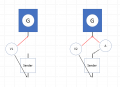
If you can't read current on your meter, then just disconnect the sender from the gauge and measure the resistance between the sender lead and ground. We can work out the current, if we know the voltage and the resistance.
Remember, current is measured in series and you generally have to use different binding posts of the meter. You can also use a low value resistor and measure the voltage across it.
There is a 99% chance that the fuse protecting the ammeter is blown.
Remember, current is measured in series and you generally have to use different binding posts of the meter. You can also use a low value resistor and measure the voltage across it.
There is a 99% chance that the fuse protecting the ammeter is blown.
This greenlee has permanent leads. You can’t remove them, no additional input jacks. Has a 20m and 200m dc current setting. I can’t get anything to read. I’m doing it properly. Red probe on input signal wire of gauge, this wire is disconnected from sender. Black probe on sender wire and again sender not connected to gauge. Basically attempting to read through the meter. I get nothing.
If you can't read current on your meter, then just disconnect the sender from the gauge and measure the resistance between the sender lead and ground. We can work out the current, if we know the voltage and the resistance.
Use (5-.2)/200 is 24 mA; Just using round numbers and assuming a 0.2V meter drop.
100 Ohms is about 48 mA. Did you measure the resistance of the sensor?
Next time you use the simpson:
1. Measure the sensor R
2. Measure the current using the SImpson and without taking the Simpson out of the circuit measure the voltage across the simpson meter leads.
3. measure the sensor voltage to ground, I suppose.
Use (5-.2)/200 is 24 mA; Just using round numbers and assuming a 0.2V meter drop.
100 Ohms is about 48 mA. Did you measure the resistance of the sensor?
Next time you use the simpson:
1. Measure the sensor R
2. Measure the current using the SImpson and without taking the Simpson out of the circuit measure the voltage across the simpson meter leads.
3. measure the sensor voltage to ground, I suppose.
Guys, I think there's a fundamental problem here...
If the sensor was 43.4ohm then calling the resistance of gauge1 X and gauge2 Y we think we know:
I1 = 1.93/43.4 = (5 - 1.93)/X and
I2 = 2.41/43.4 = (5 - 2.41)/Y
Therefore:
I1 = 44.47mA & X = 69.04ohm
I2 = 55.53mA & Y = 46.64ohm
Assuming all is linear X and Y in parallel =
(46. 64 * 69.04)/(46.64 + 69.04) = 27.84ohm
and therefore the current is:
5/(43.4 + 27.84) = 70.2mA apportioned by ratio X:Y
I.e X gets:
46.64/(69.04 + 46.64) * 70.2 = 28.3mA
and reads low by (44.47-28.3)/44.47 = 36%
And Y gets:
69.04/(69.04 + 46.64) * 70.2 = 41.9mA
and reads low by (55.53 - 41.8)/55.53 = 24.5%
But @immusicman says they both read about 17% low... So where's the fallacy in the argument?
I think its in the original assumption that both gauges use the external 5v as the reference, whereas I think one or both use their own internal references.
We need to know - to start with - what are the total and individual currents when both gauges are in circuit. And what is the open circuit voltage for each gauge when not connected to the sender.
Guys, I think there's a fundamental problem here...
If the sensor was 43.4ohm then calling the resistance of gauge1 X and gauge2 Y we think we know:
I1 = 1.93/43.4 = (5 - 1.93)/X and
I2 = 2.41/43.4 = (5 - 2.41)/Y
Therefore:
I1 = 44.47mA & X = 69.04ohm
I2 = 55.53mA & Y = 46.64ohm
Assuming all is linear X and Y in parallel =
(46. 64 * 69.04)/(46.64 + 69.04) = 27.84ohm
and therefore the current is:
5/(43.4 + 27.84) = 70.2mA apportioned by ratio X:Y
I.e X gets:
46.64/(69.04 + 46.64) * 70.2 = 28.3mA
and reads low by (44.47-28.3)/44.47 = 36%
And Y gets:
69.04/(69.04 + 46.64) * 70.2 = 41.9mA
and reads low by (55.53 - 41.8)/55.53 = 24.5%
But @immusicman says they both read about 17% low... So where's the fallacy in the argument?
I think its in the original assumption that both gauges use the external 5v as the reference, whereas I think one or both use their own internal references.
We need to know - to start with - what are the total and individual currents when both gauges are in circuit. And what is the open circuit voltage for each gauge when not connected to the sender.
My 18 to 20% is an estimate because there are only 5 bars on oem gauge vs 3 times that on the other. And I can’t tell if the tank is all the way full. But it reads full on both gauges. So don’t take my word for it. I can’t get it drained without riding it, which I can’t now as I have the bike apart in more ways than one.
Guys, I think there's a fundamental problem here...
If the sensor was 43.4ohm then calling the resistance of gauge1 X and gauge2 Y we think we know:
I1 = 1.93/43.4 = (5 - 1.93)/X and
I2 = 2.41/43.4 = (5 - 2.41)/Y
Therefore:
I1 = 44.47mA & X = 69.04ohm
I2 = 55.53mA & Y = 46.64ohm
Assuming all is linear X and Y in parallel =
(46. 64 * 69.04)/(46.64 + 69.04) = 27.84ohm
and therefore the current is:
5/(43.4 + 27.84) = 70.2mA apportioned by ratio X:Y
I.e X gets:
46.64/(69.04 + 46.64) * 70.2 = 28.3mA
and reads low by (44.47-28.3)/44.47 = 36%
And Y gets:
69.04/(69.04 + 46.64) * 70.2 = 41.9mA
and reads low by (55.53 - 41.8)/55.53 = 24.5%
But @immusicman says they both read about 17% low... So where's the fallacy in the argument?
I think its in the original assumption that both gauges use the external 5v as the reference, whereas I think one or both use their own internal references.
We need to know - to start with - what are the total and individual currents when both gauges are in circuit. And what is the open circuit voltage for each gauge when not connected to the sender.
Rely on the readings I got. Not the subjective report from me lol. I can’t judge the accuracy on both gauges comparing them. There has to be a 20% change for the oem gauge to drop one bar graph reading. Makes it hard to compare. Both are on at full. I would think the new gauge and oem gauge would reach empty at a similar time being they are 233 and 240 ohm respectively. The 233 is the new gauge. May reach empty a tiny bit sooner. But likely close enough. Can we come up with a plan for the readings we have?
With the gauge disconnected from sender, measure the voltage, using your DM20, at the gauge connection for the sender to ground.
While still measuring the voltage at the gauge, use the analog meter to measure the current from gauge to sender. Voltage should drop, record voltage & current.
With the gauge disconnected from sender, measure the voltage, using your DM20, at the gauge connection for the sender to ground.
While still measuring the voltage at the gauge, use the analog meter to measure the current from gauge to sender. Voltage should drop, record voltage & current.

 Facebook
 Google
 GitHub
 Linkedin