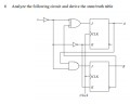
I have to find the truth table of the circuit here but can't really get my head around exactly what it's meant to do. Any help would be greatly appreciated =D
Assume a state to start with, for example both JKs outputs at "0".
Then start drawing a state diagram assuming first clock input is "0" and
walk thru all the states as you give it succesive clocks. Then assume input
is "1" and walk thru all those states to see where they transition and connect
into your state diagram.
You can verify your derivation with an online logic simulator.
As you can see this circuit only changes on a clock edge.
How is there any learning if you do the work for him?
The task is to specify for all combinations of {x, A, B} what will happen on the clock edges to {A, B}. That is what will their next state be. This will depend on the JK inputs to FFA and FFB just before the arrival of the clock edge. You might want to start with the truth table for a single JK FF. After you understand that case you can proceed to the more complicated case. Here is one of the top Google hits for "JK flip flop"
Assume a state to start with, for example both JKs outputs at "0".
Then start drawing a state diagram assuming first clock input is "0" and
walk thru all the states as you give it succesive clocks. Then assume input
is "1" and walk thru all those states to see where they transition and connect
into your state diagram.
You can verify your derivation with an online logic simulator.
As you can see this circuit only changes on a clock edge.
I'm going to assume that the diagram you show is just for illustration, and that you aren't claiming that it is the solution.
The diagram is for a Mealy machine, which is likely to confuse the TS since that is not what they have. In fact, their machine doesn't have a defined output at all, so it will only have transitions between states.
Also, your analysis approach doesn't work in general. You can't fix the input at 0 and run through the machine and then fix the input at 1 and run through the machine. You usually won't get to all of the states that way -- there will usually be states that can only be reached by a particular sequence that is a combination of 0's and 1's.
But you don't have to really walk through anything. Just set up the transition table by starting with the state variables and inputs (a total of eight rows for this problem), then find the J and K values for each FF, then determine the next state that results. Since it asks for a table and not a diagram, at that point you are done.
I'm going to assume that the diagram you show is just for illustration, and that you aren't claiming that it is the solution.
The diagram is for a Mealy machine, which is likely to confuse the TS since that is not what they have. In fact, their machine doesn't have a defined output at all, so it will only have transitions between states.
Diagram just a state machine pictorial example, nothing more. Maybe I should
have stated this is how you draw arrows and circles... example....
I think you are correct as the analysis does not take into account start state
indeterminacy. Nor does it account for the fact its edge triggered, Mealy
machine, so no fdbk change from clk is relative to the current clock edge.
Only next edge does the fdbk from prior clk matter.
But that begs the question, the circuit can only take on a finite number of states. Given
it has one input, and of course finite feedback # states, I still think it will capture all
states by clocking thru all states with a "0" then do same for "1"....? I must be missing
something here. Of course for completeness, as a chk, start states would have to be tried
to insure all states captured....Then my argument collapses.
This seems to expand on the testing of FSMs (for my benefit) -
 Facebook
 Google
 GitHub
 Linkedin
 21.3 KB Views: 18
") example....
example....


