Finding the Ripple Voltage - Half/Full Wave Rectifiers

Thread Starter

justinw23

Joined Sep 11, 2018
10
Hello all,
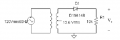
I am struggling with finding a capacitor for a half wave rectifier smoothing circuit seen below with a Vin = 120Vrms60Hz and R = 10000 such that Vr(pp) is less than 5% of the DC output voltage.
So far, I have set up Vr/Vpk = 0.5 = 1/(f*C*R) where C = 33.333 uF. I am given, in my lab kit, the following capacitors to choose from for this experiment (uF):
0.001, 0.015, 0.047, 0.1, 1.0, 10.0, 47.0, and 100.0μF. I am also required to find the ripple percentage of said capacitor I have chosen. I know I am on the cusp of the answer, just not quite there. Any help or tips would be greatly appreciated!
 

Attachments

MrChips

Joined Oct 2, 2009
30,795
So you have calculated C = 33μF
The closest you have in your kit is 47μF.
Now use that and rework the formula to find the ripple voltage.
 

Thread Starter

justinw23

Joined Sep 11, 2018
10
So you have calculated C = 33μF
The closest you have in your kit is 47μF.
Now use that and rework the formula to find the ripple voltage.

So given C = 47 uF, Vpk = 2*12.6*Vrms=2*12.6*120V = 3024 V.
Therefore, Vr = 3024 V/ (60Hz * 47 uF * 10000 Ohms ) = 107.234 V

Would the ripple percentage just be Vr/Vdc * 100?
 

Thread Starter

justinw23

Joined Sep 11, 2018
10
Learn to check your results and see if they make any sense.
I am asking because I am confused because my professor hasn't lectured on ripple voltages and I am struggling with the text. I can just go elsewhere to find help in understanding and interpreting my answers.
 

crutschow

Joined Mar 14, 2008
34,412
As MrChips noted, you need to see if your results make sense.
Just blindly plugging values into formulas is not the way to learn electronics.
You need to think about what the circuit is doing, what the expected output should be, and do the formulas make sense.

Does 3024V sound like a reasonable output from this circuit?
 
Last edited:

MrChips

Joined Oct 2, 2009
30,795
I am asking because I am confused because my professor hasn't lectured on ripple voltages and I am struggling with the text. I can just go elsewhere to find help in understanding and interpreting my answers.
This has nothing to do with what your professor has taught you or not taught you.

Look at the input voltage. It is 120VAC rms.
Does it make any sense to have an end result of 3024V?
 

Thread Starter

justinw23

Joined Sep 11, 2018
10
As MrChips noted, you need to see if your results make sense.
Just blindly plugging values into formulas is not the way to learn electronics.
You need to think about what the circuit is doing and what the expected output should be.

Does 3024V sound like a reasonable output from this circuit?
No it doesn't. I thought I had an error in finding my Vpk value. Vpk = Vrms/2. If I have a transformer stepping up the voltage from Vrms to 12.6Vrms, that would make Vpk = 12.6 Vrms / 2 = 6.3 Vrms = 6.3 * 120 = 756 Volts. Which still sounds unreasonable. I am not understanding how I am calculating clearly unreasonable output peak voltages? I am confused.
 

crutschow

Joined Mar 14, 2008
34,412
Your transformer output voltage is 12.6Vrms.
Why are you using 120V in your equations, which is the transformer input voltage?
 

Thread Starter

justinw23

Joined Sep 11, 2018
10
Your transformer output voltage is 12.6Vrms.
Why are you using 120V in your equations, which is the transformer input voltage?
I clearly misinterpreted how the transformer was affecting the circuit. I evaluated the circuit as if the transformer was stepping up the voltage by a factor of 12.6. That is my mistake.
 

Thread Starter

justinw23

Joined Sep 11, 2018
10
I clearly misinterpreted how the transformer was affecting the circuit. I evaluated the circuit as if the transformer was stepping up the voltage by a factor of 12.6. That is my mistake.
Re-evaluating the problem, still using C = 47 uF, I have calculated a peak voltage of 25.2 V and a ripple voltage of 0.8936 V. The DC output voltage is 8.0214 V.
 

crutschow

Joined Mar 14, 2008
34,412
I evaluated the circuit as if the transformer was stepping up the voltage by a factor of 12.6.
For future reference, a single number at a transformer input or output is usually the voltage for that winding.
Turns ratio is usually given with a colon between numbers, such a 10:1 for a turns ratio of ten-to-one between windings.
 

Thread Starter

justinw23

Joined Sep 11, 2018
10
For future reference, a single number at a transformer input or output is usually the voltage for that winding.
Turns ratio is usually given with a colon between numbers, such a 10:1 for a turns ratio of ten-to-one between windings.
Thank you for this piece of information.
 

MrChips

Joined Oct 2, 2009
30,795
Re-evaluating the problem, still using C = 47 uF, I have calculated a peak voltage of 25.2 V and a ripple voltage of 0.8936 V. The DC output voltage is 8.0214 V.
Did you see the diagram in post #11?

If the input AC voltage is 12.6VAC rms, how did you arrive at a peak voltage of 25.2V?
 

MrChips

Joined Oct 2, 2009
30,795
Forget about half-wave or full-wave rectifier circuit.

What is the peak voltage given the rms voltage?

Vice-versa. What is the rms voltage given the peak voltage?
 
Top