Facebook
 Google
 GitHub
 Linkedin
Hi everyone,
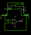
I am currently working on a home automation project where I am trying to determine the state of an electric automatic gate opener.
The actuating arm has 5 wires, with 2 of them being the closed state reed switch; although as I have found it is not just a simple reed switch, it is a reed switch with 2 transistors and has an input of 24v (don't ask me how i found out)

I have replaced the 2 transistors and the gate is once again working . During the repair process i jotted down the wiring diagram of the circuit so hopefully I can somehow get a state from it (either NO or NC) that i can then integrate with Tasmota running on a d1 mini.
Attached is a screenshot of the circuit in Circuitjs1, and when the switch is closed the yellow wire drops approximately 1v.
If anyone could help me with a circuit that won't fry the reed circuit again it would be really appreciated
Thanks,
Meesen0743
I am currently working on a home automation project where I am trying to determine the state of an electric automatic gate opener.
The actuating arm has 5 wires, with 2 of them being the closed state reed switch; although as I have found it is not just a simple reed switch, it is a reed switch with 2 transistors and has an input of 24v (don't ask me how i found out)
I have replaced the 2 transistors and the gate is once again working . During the repair process i jotted down the wiring diagram of the circuit so hopefully I can somehow get a state from it (either NO or NC) that i can then integrate with Tasmota running on a d1 mini.
Attached is a screenshot of the circuit in Circuitjs1, and when the switch is closed the yellow wire drops approximately 1v.
If anyone could help me with a circuit that won't fry the reed circuit again it would be really appreciated
Thanks,
Meesen0743
Attachments
-
 39.2 KB Views: 17