Facebook
 Google
 GitHub
 Linkedin
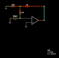
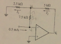
Hey Guys! I calculate the i1 and i2 currents and Vout. They gave me a different value from the simulated one. I simulate them on Falstad Circuit and they said that the Vout is -13.75 and i2 is 2mA.
See attachment.
Thanx.
Juan.
See attachment.
Thanx.
Juan.
Attachments
-
 411.3 KB Views: 12