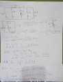
Find The Currents From Every Branch

dl324

Joined Mar 30, 2015
16,921
Welcome to AAC!

For homework, you need to show your best effort before anyone can try to guide you.

Circuit in question:
bab214570f247b9e2e7e293b797d7c14.JPG
 

Thread Starter

joe809

Joined Mar 4, 2018
32
Welcome to AAC!

For homework, you need to show your best effort before anyone can try to guide you.

Circuit in question:
View attachment 147568
That's the problem. I only got the voltage for the whole circuit which is 10.7 V. The voltage on R2 is 18V. Now, I don't know how to continue this. I thought that R3 and R4 would be 9 Amps as well since they are in parallel.
 

Thread Starter

joe809

Joined Mar 4, 2018
32
Now that I posted that reply. I think that I can used the voltage 10.77 from the whole circuit and use it to find i5 and i6. So, i5 = 5.385 and i6 = 1.795. Now, this is where I am stuck with the i4, i3, i1, and i2.
 

WBahn

Joined Mar 31, 2012
30,058
That's the problem. I only got the voltage for the whole circuit which is 10.7 V.
What do you mean by "voltage for the whole circuit"? That 10.7 V is the voltage at what point relative to what point? There is nothing in that diagram that gives a hint where this "whole circuit" voltage is.

The voltage on R2 is 18V.
Does that make sense?

If R2 is in series with a 9 A current source, how much current is flowing through R2?

If R2 is 7 Ω and has that much current flowing through it, then what must the voltage be across is?

Now, I don't know how to continue this. I thought that R3 and R4 would be 9 Amps as well since they are in parallel.
The VOLTAGE across parallel components is the same. There is no such constraint on the currents through them.

The 9 A current coming up out of the current source splits at the top of R2, some of it going left and some of it going right. Each of those two currents split again as they go down the four remaining vertical branches. What do you know about the sum of those four currents relative to the 9 A?
 

bushrat

Joined Nov 29, 2014
209
It can be easier if you redraw the circuit.
Since you already know how to calculate parallel components, calculate using differently drawn schematic.
Untitled.jpg
Both circuits are same (sorry, I added ground to the new one, has no purpose in calculations or direction of current, ignore it).
 

Thread Starter

joe809

Joined Mar 4, 2018
32
What do you mean by "voltage for the whole circuit"? That 10.7 V is the voltage at what point relative to what point? There is nothing in that diagram that gives a hint where this "whole circuit" voltage is.


Does that make sense?

If R2 is in series with a 9 A current source, how much current is flowing through R2?

If R2 is 7 Ω and has that much current flowing through it, then what must the voltage be across is?


The VOLTAGE across parallel components is the same. There is no such constraint on the currents through them.

The 9 A current coming up out of the current source splits at the top of R2, some of it going left and some of it going right. Each of those two currents split again as they go down the four remaining vertical branches. What do you know about the sum of those four currents relative to the 9 A?
I'm sorry. I am starting to learn KVL, KCL, Ohm's law at the moment. The 10.77 volts I got it by doing R6 and R5 parallel and adding it to R1. Then R3 and R4 paralle. After that I used the current divider to get the voltage. That is how I got 10.77. Like I said before, I just noticed that i5 and i6 are 10.77 volts because they are parallel to the voltage from the current source (This is what I am not sure if that is how it is described).
 

Thread Starter

joe809

Joined Mar 4, 2018
32
It can be easier if you redraw the circuit.
Since you already know how to calculate parallel components, calculate using differently drawn schematic.
View attachment 147572
Both circuits are same (sorry, I added ground to the new one, has no purpose in calculations or direction of current, ignore it).
I feel that is more complicated to me because I'm still learning the basics. The program I used to create the circuit is only to show you what circuit I have to work on. I don't even know 100% how to use it properly.
 

bushrat

Joined Nov 29, 2014
209
In the redrawn circuit, its easier to find total resistance, (series, parallel, and combination of both). Once you have that, you can use Ohm's law to solve the rest. Post your answer and someone will gladly help you guide in right direction.
 

Thread Starter

joe809

Joined Mar 4, 2018
32
In the redrawn circuit, its easier to find total resistance, (series, parallel, and combination of both). Once you have that, you can use Ohm's law to solve the rest. Post your answer and someone will gladly help you guide in right direction.
I think the total resistance is 8.2 ohms (if I did it right). After that I don't know what to do with the total resistance.
 

bushrat

Joined Nov 29, 2014
209
I don't know where you got 10.77, but it doesn't sound right. Maybe because you got mixed up with branching circuit..
Now that you know the total current, and voltage, calculate how much current (and voltage) each resistor drops.
 

Thread Starter

joe809

Joined Mar 4, 2018
32
I don't know where you got 10.77, but it doesn't sound right. Maybe because you got mixed up with branching circuit..
Now that you know the total current, and voltage, calculate how much current (and voltage) each resistor drops.
The problem I have with your circuit model is that I am not allowed to make any changes to the circuit. I have to work with it the way it is. As of the 10.77 volts, I found that by doing this from the original circuit.
R3(R4)/R3+R4 = 1.5
R6(R5)/R6+R5 = 2.92
2.92 + R1 = 5.92
Now, [1.5(5.92)/1.5+5.92]x9 = 10.77 V
 

WBahn

Joined Mar 31, 2012
30,058
I think the total resistance is 8.2 ohms (if I did it right). After that I don't know what to do with the total resistance.
If you mean the total resistance as seen by the current source, then this is correct. You really do need to indicate WHERE an equivalent resistance is being calculated from, because each component, in general, sees a different equivalent resistance from it's vantage point.

So now, as far as your 9 A current source is concerned, it is connected to a resistance of 8.2 Ω. Can you determine what the voltage is across the current source (which is the same as the voltage across the equivalent resistance)?
 

WBahn

Joined Mar 31, 2012
30,058
V=iR = 9(8.2)= 73.8V? I thought that the total voltage was 10.77.
Why do you think that?

We can't help you figure out what you did wrong in your calculations unless you show your work for how you got that result. The description you gave really gives no hint as to how you came up with that number. Show your work!
 

WBahn

Joined Mar 31, 2012
30,058
The problem I have with your circuit model is that I am not allowed to make any changes to the circuit.
When you move components around on the schematic you aren't changing the circuit unless you change the connections. Bushrat didn't change any of the connections. Now, as to whether his representation is "easier" to work with or not is a matter of opinion. Clearly HE sees it as easier, but that's because it matches a circuit topology that makes the clearest sense to HIM. Different people see things different ways.

[/QUOTE]

I have to work with it the way it is. As of the 10.77 volts, I found that by doing this from the original circuit.
R3(R4)/R3+R4 = 1.5
R6(R5)/R6+R5 = 2.92
2.92 + R1 = 5.92
Now, [1.5(5.92)/1.5+5.92]x9 = 10.77 V[/QUOTE]

Let's walk through this:

R3(R4)/R3+R4 = 1.5 Ω

First, you need to start properly tracking units. The value 1.5 is NOT a resistance, it is just a number.

Second, what you've written and what you meant are two very different things. What you wrote is

{[R3(R4)]/R3} + R4 = 1.5 Ω

Which reduces to simply

R4 + R4 = 12 Ω

What you MEANT to write was

R3(R4)/(R3+R4) = 1.5 Ω

You NEED to keep order of operations in mind. This kind of sloppiness WILL get you into trouble.

You made the same mistake on the next one.

Your "total voltage" is the voltage at the top-right node relative to the bottom node. Okay. Fine. But there is nothing that sticks out making it obvious that this is the "total voltage". You need to be very explicit about what a voltage means -- where it is measured at, either between what to nodes are what node it is measured at relative to a specified common node (which you haven't specified a common node anywhere).
 

WBahn

Joined Mar 31, 2012
30,058
Please upload your images to your post (using the Upload a File button). This forum is archival in nature and there is no guarantee that that image will be available at that link next week, let along in a decade or two. Plus, many people are not going to just blindly click on a third party link.
 

Thread Starter

joe809

Joined Mar 4, 2018
32
Please upload your images to your post (using the Upload a File button). This forum is archival in nature and there is no guarantee that that image will be available at that link next week, let along in a decade or two. Plus, many people are not going to just blindly click on a third party link.
 

Attachments

Top