Find current through 4ohm resistor using superposition theorem,

ericgibbs

Joined Jan 29, 2010
18,766
hi Sajan,
Welcome to AAC.
Could you please post your attempt at answering the question, so that we can check your .work.?
E
 

wayneh

Joined Sep 9, 2010
17,496
I would assume it does matter unless/until I could show otherwise. Do you know anything about the meter? Oh wait, is that a 100mA current source?
 

WBahn

Joined Mar 31, 2012
29,978
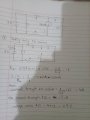
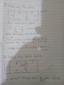
on finding equivalent resistance with voltage source only, does the 5 ohm resistance count or not?

View attachment 167783
Moderators note : cropped image and posted full size
The traditional way of doing superposition, particularly for beginners, is to do a separate analysis with exactly one source turned on and the others turned off. You have three sources (two voltage sources and one current source).

Treat them as three separate problems. For each one, redraw the circuit with the other two sources turned off, which means replacing voltage sources with a short circuit and current sources with an open circuit. Then analysis the resulting circuit to find the voltages/currents of interest.

Do that and see if the answer to your question jumps out at you. If not, post your redrawn circuit and we can explore further.
 

Thread Starter

Sajan Gurung

Joined Dec 20, 2018
33
Thank you everybody for reply, i can solve basic problems using superposition theorem. But in this perticular circuit i am just confused because of that current source with resistor, while taking only voltage soucre by short circuiting current source the 5 ohm resistor is left hanging which is confusing me. I have solved without taking 5 ohm, please correct me if i have made mistake while solving, thank you.
 

wayneh

Joined Sep 9, 2010
17,496
I believe you are correct that you could consider the 5Ω resistor as if it was internal to the current source. By definition, the current in that leg is 100mA no matter what, right? The value of that resistor doesn't matter.
 

Thread Starter

Sajan Gurung

Joined Dec 20, 2018
33
Ok, thank you,
But
By definition, the current in that leg is 100mA no matter what, right?
I didn't understand this. Do you mean that current in that leg could have a different value due to other sources?
I mean the value will be different of course due to other sources. I think i didn't get what you mean there?
 

crutschow

Joined Mar 14, 2008
34,282
By definition the current through a current source is a fixed value (100mA in this case), thus the current through the 5Ω resistor is independent of any other source voltages or currents.
 

MrAl

Joined Jun 17, 2014
11,389
Hi,

In cases where you have a theoretical question that involves only part of the circuit, you can often simplify the circuit and then solve the simpler circuit and see what that leads to.

For the question of a current source in series with a resistor, place a current source in series with a 5 ohm resistor and another 5 ohm resistor. So now you have simply a current source pushing the current through two resistors. Now try to find the voltage across each resistor.
What else you you know? You know that the current through a series circuit is the same though all elements of the series circuit. That information can allow you to calculate the voltage across each of those two resistors using Ohm's Law. You can then start to understand what it means to have a current source in series with a resistor.
 

WBahn

Joined Mar 31, 2012
29,978
I have done assuming 5 ohm resistor doesnot take part while taking only voltage source.
You made one of the classic mistakes because you, like so many people, won't track your units. Instead you just throw whatever units you would like the answer to have onto the result and blindly proceed without even asking if it makes sense.

In your first attachment (for the 3 V source) had you tracked your units in calculating your resistance, you would have gotten 1.8 Ω. Had you then tracked your units in finding the current you would have gotten a total current of 1.67 A, not 1.67 mA. But because you are probably used to working problems that have answers in milliamps, you just tacked on the unit that you wanted it to have and, as a result, ended up with an answer that is wrong by three orders of magnitude!

You should always ask if your answers make sense. Does it make sense that a circuit having resistances in the single-digit ohm range and a voltage source in the single-digit volt range would have currents in the milliamp range?

Next you blindly threw the current division formula at the problem and got that nearly all of the current flowing in the battery is going through the 8 Ω resistor and not the 2 Ω resistor.

Does that make sense?

And why are you only taking into account the 8 Ω? What about the other 10 Ω that it is in series with?

Then you get a voltage across the 4 Ω resistor of 5.3 V. Does this make sense (given that the circuit is powered by a 3 V source).

Your drawing shows the voltage across the 4 Ω resistor as being positive on the left side relative to the right side. So a voltage across it of 5.3 V would mean that the current would be flowing in it from left to right. Does that make sense?

Finally, your drawing shows a current in the battery of 1.3 mA, but your work indicated 1.67 mA.

Consider all of the mistakes you have made in just this first image. You need to REALLY pay attention to details.

You need to always, always, ALWAYS track your units through each and every step of your work and you need to always, always, ALWAYS ask if the answer makes sense.

You also made your analysis work much more difficult than it needs to be. Just do KVL around the outer loop and you can get the current in the 4 Ω resistor immediately as being (right-to-left) 3 V / 18 Ω = 167 mA, yielding a voltage across it (using the polarity as you've defined it in your drawing) of -667 mV.
 

WBahn

Joined Mar 31, 2012
29,978
Thank you everybody for reply, i can solve basic problems using superposition theorem. But in this perticular circuit i am just confused because of that current source with resistor, while taking only voltage soucre by short circuiting current source the 5 ohm resistor is left hanging which is confusing me. I have solved without taking 5 ohm, please correct me if i have made mistake while solving, thank you.
A resistor in series with a current source is not visible to the rest of the circuit (it is 'masked' by it). This is because the current source will produce whatever voltage is required to deliver the constant current.

The same is true of a resistor in parallel with a voltage source since the source will produce whatever current is required to deliver the constant voltage.

This does not mean that they can always be ignored. The rest of the circuit may not be able to tell that they are there, but they DO affect the total power dissipated in the circuit, so if that is what you are being asked about, you can't ignore them. But, with just a bit of care, you can still simply the circuit to get the other voltages and currents and then deal with them separately.
 

Thread Starter

Sajan Gurung

Joined Dec 20, 2018
33
Hi,

In cases where you have a theoretical question that involves only part of the circuit, you can often simplify the circuit and then solve the simpler circuit and see what that leads to.

For the question of a current source in series with a resistor, place a current source in series with a 5 ohm resistor and another 5 ohm resistor. So now you have simply a current source pushing the current through two resistors. Now try to find the voltage across each resistor.
What else you you know? You know that the current through a series circuit is the same though all elements of the series circuit. That information can allow you to calculate the voltage across each of those two resistors using Ohm's Law. You can then start to understand what it means to have a current source in series with a resistor.
Thank you, I understood what you mean.
 

Thread Starter

Sajan Gurung

Joined Dec 20, 2018
33
You made one of the classic mistakes because you, like so many people, won't track your units. Instead you just throw whatever units you would like the answer to have onto the result and blindly proceed without even asking if it makes sense.

In your first attachment (for the 3 V source) had you tracked your units in calculating your resistance, you would have gotten 1.8 Ω. Had you then tracked your units in finding the current you would have gotten a total current of 1.67 A, not 1.67 mA. But because you are probably used to working problems that have answers in milliamps, you just tacked on the unit that you wanted it to have and, as a result, ended up with an answer that is wrong by three orders of magnitude!

You should always ask if your answers make sense. Does it make sense that a circuit having resistances in the single-digit ohm range and a voltage source in the single-digit volt range would have currents in the milliamp range?

Next you blindly threw the current division formula at the problem and got that nearly all of the current flowing in the battery is going through the 8 Ω resistor and not the 2 Ω resistor.

Does that make sense?

And why are you only taking into account the 8 Ω? What about the other 10 Ω that it is in series with?

Then you get a voltage across the 4 Ω resistor of 5.3 V. Does this make sense (given that the circuit is powered by a 3 V source).

Your drawing shows the voltage across the 4 Ω resistor as being positive on the left side relative to the right side. So a voltage across it of 5.3 V would mean that the current would be flowing in it from left to right. Does that make sense?

Finally, your drawing shows a current in the battery of 1.3 mA, but your work indicated 1.67 mA.

Consider all of the mistakes you have made in just this first image. You need to REALLY pay attention to details.

You need to always, always, ALWAYS track your units through each and every step of your work and you need to always, always, ALWAYS ask if the answer makes sense.

You also made your analysis work much more difficult than it needs to be. Just do KVL around the outer loop and you can get the current in the 4 Ω resistor immediately as being (right-to-left) 3 V / 18 Ω = 167 mA, yielding a voltage across it (using the polarity as you've defined it in your drawing) of -667 mV.
Thank you for evaluating my solution. And I realized that I made silly mistakes that I could have easily avoided if I kept track of units. And regarding the current division, yes I did forget to take into account other resistors that were in series with 8 ohm resistors and the current on 4 ohm resistors would be flowing from right to left. And yes I agree that the problem would have been easier if I applied KVL in outer loop finding current easily in 4 ohm resistors thus voltage. And also "Does that make sanse?" is actually quite helpful. Again thank you for your time and effort for explaining my mistakes.
 

Thread Starter

Sajan Gurung

Joined Dec 20, 2018
33
A resistor in series with a current source is not visible to the rest of the circuit (it is 'masked' by it). This is because the current source will produce whatever voltage is required to deliver the constant current.

The same is true of a resistor in parallel with a voltage source since the source will produce whatever current is required to deliver the constant voltage.

This does not mean that they can always be ignored. The rest of the circuit may not be able to tell that they are there, but they DO affect the total power dissipated in the circuit, so if that is what you are being asked about, you can't ignore them. But, with just a bit of care, you can still simply the circuit to get the other voltages and currents and then deal with them separately.
So a resistor in series with current source will have a constant current value and a resistor in parallel with voltage source will have constant voltage value for a single current source and voltage source respectively even when there are many current and voltage sources and other things forming a complex circuit right? If yes, then that's what I am asking. Thank you for your reply.
 

MrAl

Joined Jun 17, 2014
11,389
So a resistor in series with current source will have a constant current value and a resistor in parallel with voltage source will have constant voltage value for a single current source and voltage source respectively even when there are many current and voltage sources and other things forming a complex circuit right? If yes, then that's what I am asking. Thank you for your reply.
Hi,

Well you can notice that if you have a voltage source in parallel with resistance, if you vary the resistance does the voltage source voltage change value? Like say a 5v ideal voltage source. What is the voltage with a 10 ohm resistor, what is the voltage with a 20 ohm resistor, what is the voltage with a 5 ohm resistor? Did the voltage change from 5v with any of those values?
 
Top