Filtering out signal level pulses

Thread Starter

algernon

Joined Aug 9, 2009
10
I have a motorised garage door opener and am trying to use a 5vdc output on the control unit to operate an electromagnetic lock on the door.

The 5vdc is at signal level and while the door is opening gives a constant 5v output. But when the door has finished moving there are pulses of +ve voltage present at the output.

I have set up a darlington array IC to take the input and switch a 12v relay but what i have found is that the relay clicks as the door is at rest due to the pulses of voltage.

Is there a way i can filter out the pulses of voltage present at the input side or output side of the darlington array?
 

Thread Starter

algernon

Joined Aug 9, 2009
10
I do not know exactly as i only have a basic multimeter. But with an LED connected on the output of the darlington it looks like it flashes once a second and for a period of what appears to be milliseconds.
 

Ron H

Joined Apr 14, 2005
7,063
Can you tolerate a turn-on delay that is a little longer than the width of the pulses that you want to filter out?
 

someonesdad

Joined Jul 7, 2009
1,583
This is possibly a dumb question since I don't know exactly what you're trying to do. It sounds like you want to actuate a solenoid that locks the door after the door closes. Why not just use a microswitch or optical switch to detect when the door is down to actuate the solenoid? If you need a delay, a simple RC circuit could provide it.
 

Thread Starter

algernon

Joined Aug 9, 2009
10
Can you tolerate a turn-on delay that is a little longer than the width of the pulses that you want to filter out?
Yes a delay of that length would be fine. This output from the door controller is actually meant to drive a flashing light unit which activates only whilst the door is in motion.

I have found with my experiments that when any type of circuit is completed through this output (pins 5 and 6), the door opener actually introduces its own delay before the start and after the end of the door motion (a couple of seconds delay when pressing the control button). I'm guessing this pause has the purpose of starting the flashing light as a warning that the door will begin motion.

There is no pause when the pins 5 and 6 are open circuit. Could it be that the pulses are there to sense a component in circuit?

So anyway this two second pause is a help because it'll make sure the electromagnet is de-energized before the door tries to move, and also makes a pulse width (or somewhat longer) delay tolerable.
 

Thread Starter

algernon

Joined Aug 9, 2009
10
This is possibly a dumb question since I don't know exactly what you're trying to do. It sounds like you want to actuate a solenoid that locks the door after the door closes. Why not just use a microswitch or optical switch to detect when the door is down to actuate the solenoid? If you need a delay, a simple RC circuit could provide it.
Yes i guess that would work when the door closes but then i would need an unlock trigger to make sure the electromagnet is de-energized before the door tries to open. I thought of using the controller's output as it would be a bit more fail-safe.
 

Ron H

Joined Apr 14, 2005
7,063
I'm generating a couple of schematics for you to try. What are the operating voltages and currents of the lock and the relay?
 

Thread Starter

algernon

Joined Aug 9, 2009
10
The lock is 12vdc and the relay operating it has a 12vdc coil (This is the relay the coil of which is switched from the darlington). Thanks for the help Ron H, i've been racking my brain over this for days.
 

Ron H

Joined Apr 14, 2005
7,063
The lock is 12vdc and the relay operating it has a 12vdc coil (This is the relay the coil of which is switched from the darlington). Thanks for the help Ron H, i've been racking my brain over this for days.
Why do you need a relay?

How much current does the lock draw?

How much current does the relay draw?
 

Thread Starter

algernon

Joined Aug 9, 2009
10
Why do you need a relay?

How much current does the lock draw?

How much current does the relay draw?
Lock draws 500mA @ 12vdc, relay draws approx 60mA. Thought of using a relay to remove the high current drawn by the lock from the darlington.
 

Thread Starter

algernon

Joined Aug 9, 2009
10
Was just checking the spec on the ULN2803a array and it states each darlington pair can handle 500mA, so i guess i can run the circuit without a relay. But i will still have the pulse problem.
 

Ron H

Joined Apr 14, 2005
7,063
I would use the relay. I don't like pushing a device to its limits. You don't need a Darlington if you use the relay, though. Any general purpose NPN like 2N3904 would suffice.
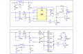
Below are two ideas. There are possibly simpler ways to do this. Maybe one of the other guys will come up with one. I'll also think on it some more.
 

Attachments

Thread Starter

algernon

Joined Aug 9, 2009
10
Thanks Ron, will get to work building the circuits on my prototyping board. I have a few questions though as i'm a bit of a novice at electronics:

1. Both your examples have a regulator converting +12vdc to +5vdc, is this because the rest of the circuit runs at signal level?

2. Is it ok to replace the 78L05 with an L78S05CV as my local vendor does not stock the former?

3. What purpose does the 1Mohm variable resistor serve?

4. Will the output part of the circuit only accept a 60mA coil or will it accept a range of values?
 

rjenkins

Joined Nov 6, 2005
1,013
If you are running a relay from a darlington, a simple R-C filter into the base of the darlington should work.

Try something like 4k7 from the signal to the base of the darlington and 10uF base to 0V.

You may have to tune the values a bit, eg. if it still pulses try 100uF or if it never turns on try a 1K resistor (and proportionally larger capacitors).

On a point of practicality, will the solenoid system still allow you to open the door if the power fails or the motor unit packs up?

The normal way of operating mechanical latches on a powered garage door is via a special link bar from the motor track to the door. It has a limited telescopic movement and pulls a bowden cable link to release the latches when the motor starts pulling the door open. This allows the manual release to be retained.
 

Thread Starter

algernon

Joined Aug 9, 2009
10
If you are running a relay from a darlington, a simple R-C filter into the base of the darlington should work.

Try something like 4k7 from the signal to the base of the darlington and 10uF base to 0V.

You may have to tune the values a bit, eg. if it still pulses try 100uF or if it never turns on try a 1K resistor (and proportionally larger capacitors).

On a point of practicality, will the solenoid system still allow you to open the door if the power fails or the motor unit packs up?

The normal way of operating mechanical latches on a powered garage door is via a special link bar from the motor track to the door. It has a limited telescopic movement and pulls a bowden cable link to release the latches when the motor starts pulling the door open. This allows the manual release to be retained.
Thanks for the info, will try the R-C filter aswell as Ron's suggestion. To answer your question about motor or power failure, this shouldn't be a problem as the electromagnet lock can be turned off easily freeing the door and allowing the manual door opener to be used.
 

Ron H

Joined Apr 14, 2005
7,063
Thanks Ron, will get to work building the circuits on my prototyping board. I have a few questions though as i'm a bit of a novice at electronics:

1. Both your examples have a regulator converting +12vdc to +5vdc, is this because the rest of the circuit runs at signal level?
It's because your input signal is 5V, so the Schmitt trigger needs to be powered from 5V. Alternately, the input signal could first be changed to 12V, or the Schmitt trigger could be made from a comparator operating on 12V.

2. Is it ok to replace the 78L05 with an L78S05CV as my local vendor does not stock the former?
L78S05CV requires a minimum load of 20mA for proper load regulation. 78L05 requires 1mA minimum.

3. What purpose does the 1Mohm variable resistor serve?
I forgot to explain that. To adjust it, start with it at minimum resistance (≈0 ohms). The relay should click with each pulse. Rotate the pot until the clicking stops.

4. Will the output part of the circuit only accept a 60mA coil or will it accept a range of values?
It will drive loads less than 60mA. If you want to go higher, we would need to adjust resistor values and/or transistor type.

Rjenkins' suggestion will probably work just fine. I told you someone else would have a simpler idea.:)
 

Thread Starter

algernon

Joined Aug 9, 2009
10
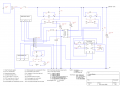
Thanks for the help Ron H and Rjenkins with the pulse filtering. Below is a schematic of the circuit i used for the project. I used Rjenkins' R-C filter in the end to keep it simple.

This circuit uses a signal level signal from the ML850 garage door opener control unit to deactivate an electromagnetic door lock allowing the door to open. The circuit also triggers a timer control module that turns on the mains (UK) voltage garage lights.

The project is completed and up and running. Thanks again.
 

Attachments

Top