 Facebook
 Google
 GitHub
 Linkedin
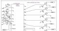
I designed and built this controller for fireworks to be computer controlled to play along with music about 10 years ago.
I used an old laptop with a parallel port to control the 5 decoder chips for a total of 90 circuits. There is an LED continuity
indicator on each FET output that is shown only on the first position. Each circuit is wired to
a 1.2 Ohm thin wire resistor that ignites a pyrogen applied over it. (Known as an e-match.) The wire burns out within milliseconds.
Additional resistance in the circuit is provided by 200 feet of wire to the e-match. The e-match has a minimum firing current of 350mA.
The system works well but occasionally fires one of the e-matches at random when the +24 V is switched on by the operator.
First the logic power to the decoders is turned on, then the software clears the port by writing all zeros to it, waiting one second and
writing it again to be sure. Then the operator is prompted to turn on the +24V (all power supplied by batteries).
Does anyone see a flaw in the design that might cause this behavior? I have had to stop using it because of this problem.
Attachments
-
 115.3 KB Views: 28
 -
 128.7 KB Views: 23


