feedback in amplifiers

Thread Starter

raks_universe

Joined Mar 15, 2009
67
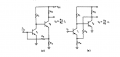
In my textbook ,it is given that , the following circuit has current-series feedback....

http://pic.ksb7.com/images/0h3swv5oi22m49rz10q.jpg

Pls explain how this(current-series feedback) occurs in the circuit,.,.,

Pls explain both sampling and feeding in this circuit...

In general, what i hav to do,if i want to sample current from o/p....(where to use resistor or wat to do)

It seems easier to explain the feedback in two port network,but i cant define wat kind of feedback is present in given amplifier circuit(without two port analysis) ,.,.,.

Pls guide me to determine the type of feedback in amplifier ckt(without changing to two port network).....

Im so confused with the feedback concept....

Plss help me....
 

retched

Joined Dec 5, 2009
5,207
As you can see, all pins of the transistor are connected to each other. SO, depending on the resulting output, the input and gate charge are changed.

So, using the resistors, you can set up a ratio on how you want the output to effect the control.
 

Audioguru

Joined Dec 20, 2007
11,248
The emitter resistor provides DC negative feedback. Since the emitter resistor is bypassed with a capacitor then the circuit has no AC negative feedback.

When the input DC voltage goes positive (or negative) then the emitter voltage also goes positive (or negative) which reduces the base emitter voltage difference therefore is negative DC feedback.

The output is the impedance of the collector resistor. The voltage gain of the transistor is reduced if the load resistance is about 10 times higher or less.
 

Thread Starter

raks_universe

Joined Mar 15, 2009
67
Thanks 4 ur replies,.,.,

But,

Can u explain how the given circuit follows current-series feedback,.,.,.,

In the given circuit,,at which place current is sampled,..???,.,.,.and at which place it is feeded,.,.???

i cannot find current sampling in this circuit....why cant i say this as voltage sampling,.,.,.,


Pls guide me,.,.:)
 

Jony130

Joined Feb 17, 2009
5,488
Re resistor adds negative feedback to the circuit for DC current.
In this circuit Vb is constant (unchanged) thanks to R1 and R2 voltage divider.
So any change in Ic current (output current) make the same change in emitter current (Ie). This change in current change voltage on Re resistor and also change Vbe because
Vbe = Vb - Ve so if Vb= onst and Ve change Vbe (input voltage) will be change to.
For example if for some reason Ie current increase, voltage drop on Re also increase and this will decrease Vbe voltages. So Ic current will decrease to because Vbe decreased.
We have similar situation if we Ic
decrease, then Ve decrease to so Vbe increase
and this increases the collector current. So circuit tends to balancing itself.
 

Ethan

Joined Feb 7, 2009
6
The feedback voltage is the voltage Ve across the resistor Re. Neglecting the base current, we have Ve = -ReIc (note the '-' sign -Ic can be consider the output collector current this is the sampled signal and the feedback signal is the voltage Ve). At input side voltage Ve is subtracted from VIN to produce Vi.
 
Last edited:

t_n_k

Joined Mar 6, 2009
5,455
Can u explain how the given circuit follows current-series feedback,.,.,.,
Why is it an example of current-series [sometimes call "series-series" feedback] in this case?

By definition ...

In current-series feedback a voltage proportional to the amplifier output [load] current is fed back in such a manner as to be in series with the input voltage.

In your schematic ...

The emitter current approximates the collector [output] current. A voltage [Ve] proportional to this current is created by the parallel combination of RE & C2.

The voltage across RE||C2 [Ve] is added algebraically [i.e. negatively] in series with Vbe to form the total input. So Vin=Ve+Vbe or Vbe=Vin-Ve.

With a constant input signal Vin, one presumably wants a constant output signal. Hence, if Ve tends to increase for whatever undesirable reasons, then Vbe decreases accordingly and the output is therefore less affected by those undesirable changes. That's negative feedback of the current-series 'variety'.
 

Thread Starter

raks_universe

Joined Mar 15, 2009
67
Thanks 4 ur replies....

Now im somewhat clear in this concept...

But...

If i am asked to give a feedback in an amplifier circuit(non feedback circuit),,,,,,,,,what i hav to do...???

In my books ,.,it is given example only for two port network(pls see attachment),.,.but how to apply that technique in amplifier circuit....

Guide me to make feedback circuit,,,.,. and also guide me "how to identify the type of feedback present"......
 

Attachments

t_n_k

Joined Mar 6, 2009
5,455
Are you considering simple transistor amplifiers?

In the preceding posts you've already been asking about the current-series feedback example - i.e. in the case of emitter resistance / impedance feedback.

I guess what you are wanting to do is translate the generic feedback forms into realistic amplifier examples.

Try searching on Google books for examples.

One book I found that might help and which had a relevant detailed preview available was .....

"Active network analysis" By Wai-Kai Chen - chapter 4

There doesn't always appear to be clear agreement on feedback terminology and its relationship to practical circuits.

This following book seems to differ somewhat from the earlier text I noted above.

"Eshbach's handbook of engineering fundamentals" By Ovid Wallace Eshbach, Byron D. Tapley, Thurman R. Poston - see Figure 12.48
 

Jony130

Joined Feb 17, 2009
5,488
There is a clear way to differentiate between the two type of feedback. If you disconnect your load, and the feedback signal goes to zero (output current goes zero), that's current feedback (load current > zero, feedback > zero ). If, on the other hand, you short the load, and the feedback goes to zero (output voltage goes zero), that's voltage feedback (load voltage > zero, feedback > zero).
The input summing is shunt when feedback connects to the same node that the input source is connects. Otherwise we have series feedback.

Voltage-shunt feedback


figure d - current-shunt
figure e - voltage-series


Attachments

Last edited:

t_n_k

Joined Mar 6, 2009
5,455
There is a clear way to differentiate between the two type of feedback. If you disconnect your load, and the feedback signal goes to zero, that's current feedback (load current > zero, feedback > zero). If, on the other hand, you short the load, and the feedback goes to zero, that's voltage feedback (load voltage > zero, feedback > zero).
The input summing is shunt when feedback connects to the same node that the input source is connects. Otherwise we have series feedback.
The distraction in circuit (b) is the collector resistor denoted as RL.

I agree this is a voltage shunt feedback example. But if you remove this resistor RL, the feedback goes to zero or is indeterminate. So one might be confused as to whether this a case of current or voltage feedback.

Probably the load in this case should be whatever is connected across Vo.
 

t_n_k

Joined Mar 6, 2009
5,455
It seems like we could use the feedback's effect on the output impedance, for example, to determine the type of feedback.
Yes - it's interesting that one of the texts I referred to in an earlier post makes reference to the type of feedback and its effect on both input and output impedance. Again - it's not easy to make a decision on this basis without some computational or experimental data at hand.

It's understandable that the OP has some problems discerning the type of feedback.

I still think Jony130's suggestion is a pretty good approach in the absence of any other knowledge of the circuit.

The same text to which I referred also makes the reasonable claim that
" .... not every feedback amplifier can be classified as being in one of the four categories."

i.e. series-series, parallel-parallel, parallel-series & series-parallel. Or whatever other equivalent terminology [incl. shunt, voltage, current] one prefers!
 
Last edited:
Top