Faulty power supply

Thread Starter

Alvin_freeman

Joined Sep 23, 2022
35
Hi guys, I have a problem, (I am a beginner)
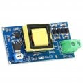
I have a Chinese made power supply (DC‑DC Boost Converter Voltage Step Up Board 1200V Adjustable DC Voltage Regulator 5-12V to 400-1200V), this power supply voltage is relevant to it's current I think, so with higher current it's voltage drops. I connect it to my photomultiplier with -800 volts output that I measured across power supply terminals after connecting lt to my photomultiplier and it's voltage driver I can see -800 volts required and recommended to drive photomultiplier. But I can't see my photomultiplier working and it products very weak signals under one volts which is not okay. But after accidentally I increased voltage to higher than -1000 volts it starts to working. But it's much higher than recommended value for PMT. Power supply minimum current is 2 Milliamps and maximum current is 20 Milliamps I found this information on it's page. So I tested it with low value resistor it's voltage significantly drops, with higher resistance voltage increases. Photomultiplier current draw is under 13 micro amps so how this small current cause voltage drops but still I see -800 volts on terminals. It has one ne555, one transformer and one lr2905z mosfet. Other thing are capacitors and resistors. I don't know this power supply design has a problem or one of these components on my power supply is faulty.
Power supply 1200 volts
 

Attachments

Last edited:

MrChips

Joined Oct 2, 2009
34,628
Let's do some quick math.

P = V x I
1000 V x 20 mA = 20 W

Is the power supply capable of supplying 20 W ?

1000 V x 1 mA = 1 W
The load would have to be
R = V / I = 1000 V / 1 mA = 1 MΩ

Don't make your test load lower than 1 MΩ.
 

Thread Starter

Alvin_freeman

Joined Sep 23, 2022
35
Let's do some quick math.

P = V x I
1000 V x 20 mA = 20 W

Is the power supply capable of supplying 20 W ?

1000 V x 1 mA = 1 W
The load would have to be
R = V / I = 1000 V / 1 mA = 1 MΩ

Don't make your test load lower than 1 MΩ.
I tested it again multiple times with 1 Megaohm resistor and it can deliver 1 milliampere. And maybe more with lower resistance. But I don't know maybe switching frequency is too low or very small (maximum 13 micro amps) can drop voltage too much or not, why PMT starts working with higer than maximum voltage recommended.
 

Thread Starter

Alvin_freeman

Joined Sep 23, 2022
35
Let's do some quick math.

P = V x I
1000 V x 20 mA = 20 W

Is the power supply capable of supplying 20 W ?

1000 V x 1 mA = 1 W
The load would have to be
R = V / I = 1000 V / 1 mA = 1 MΩ

Don't make your test load lower than 1 MΩ.
Thank you Mrchips again power supply was okay and correctly working. I don't know but somehow default resistors was not working or I couldn't figure it out how I can connect and extract output from them but I found someone used higher value resistors for PMT voltage divider circuit and it's working. Maybe it has a relationship with a load resistor somehow But i couldn't figure it out.
 

Thread Starter

Alvin_freeman

Joined Sep 23, 2022
35
Show us a photo of the PMT and provide any links to its description.
A PMT circuit might look like this:

View attachment 342480
It is working right now but with default setup it's output is slow with low voltage pulses some of them are high. With high value resistor 10 megaohm for each dynode and the last one 4.7 megaohm. which used before by other people, It shows more pulses with higher amplitude. I don't know it's noise or it's gain incrased.
 
Last edited:

MrChips

Joined Oct 2, 2009
34,628
What is the PMT detecting? Are you using the PMT in pulse mode or current mode? What kind of scintillator are you using?
Is the face of the PMT covered?
 

Thread Starter

Alvin_freeman

Joined Sep 23, 2022
35
What is the PMT detecting? Are you using the PMT in pulse mode or current mode? What kind of scintillator are you using?
Is the face of the PMT covered?
It's a package of csi(tl) crystal and pmt itself. Covered with metal shield. To detect gamma rays, I use oscilloscope, so it's on pulse mode I think.
 

Thread Starter

Alvin_freeman

Joined Sep 23, 2022
35
That is what I suspected.
How large is the PMT or scintillator?
The rates from background radiation are very low. If the rates increase when the HV is increased then you could be hitting HV breakdown.
I knew that it must be about 400 CPM or maybe 800 I didn't count them. It's about a 1 to 5 centimeters. It has very high noise around 400 millivolts, maybe from power supply and other noise sources like 5G cell tower or wifi but currently I am working on voltage divider and I want to figure it out how it's working.
 

Thread Starter

Alvin_freeman

Joined Sep 23, 2022
35
For that size detector, 600 CPM is 10 counts/s which is about 100 times too high.
How I can eliminate noise MrChips, If i connect low pass filter with a resistor to the output, for example 1 Megaohm and 47 nanofards, current direction will change and it doesn't flow across load resistor or if i connect low pass filter before load resistor can it flow across capacitor? I am confused right now? I see noise around 20 kilohertz. I saw it's filter out signal also
 

MrChips

Joined Oct 2, 2009
34,628
Show us the circuit on the base of the PMT.
Is the HV positive or negative?
The signal is usually AC coupled through a series capacitor. The signal is positive going for negative supply and vice versa. The signal should look somewhat like this for positive HV.

1739473584808.png
 

Thread Starter

Alvin_freeman

Joined Sep 23, 2022
35
Show us the circuit on the base of the PMT.
Is the HV positive or negative?
The signal is usually AC coupled through a series capacitor. The signal is positive going for negative supply and vice versa. The signal should look somewhat like this for positive HV.

View attachment 342501
Output is okay, I can use it right now it has around 1 volts noise. If you mean voltage divider you can't trace wires from pictures because there is many wires but it's a simple voltage divider recommended by datasheet. Connections are okay because i see it's out put on oscilloscope. But noise is too high maybe from power supply which i must filter it out. Yes output is like that picture but a little bit more noise. No supply voltage is negative the output is negative also. AC coupled cap didn't decrease noise unfortunately I tested it with low and high values.
 
Last edited:

MrChips

Joined Oct 2, 2009
34,628
Measure the frequency of the oscillator in the DC-DC converter. Trigger the oscillosope on this signal.
Then you will be able to see this same frequency in the PMT output.
 

MrChips

Joined Oct 2, 2009
34,628
If your PMT base looks like this, then your signal at the anode is on the GND side. You can use a terminating resistor on the output.

PMT base resistors.jpg
 
Top