Fake RTC 32768Hz (32kHz) crystal oscillators ? Or special setup for them to work?

MrChips

Joined Oct 2, 2009
35,279
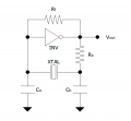
Here is a circuit I have used.

1700417439939.png

Rf = 10MΩ
Rs = 220kΩ
Ca = 33pF trimmer cap
Cb = 22pf
INV = MC14584B HEX Schmitt Trigger Inverter

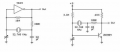
Here are similar circuits off the web.

1700417774541.png
 

Thread Starter

q12x

Joined Sep 25, 2015
2,245
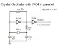
I try it already (my version) :
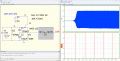
crystal Oscillator with 7404 in parallel.jpg
For your MC14584B HEX Schmitt Trigger Inverter
I tried with a Schmitt Trigger Inverter as well, and it work right away, but my personal and subjective impression is that inverter might oscilate by itself and interfere with the crystal oscilations. I had no proper way of reading so I rely on my good sense of things.
To be able to read it properly, I might have to build a FF divider, and then, read the result. Thats my idea what to do next.
Its very challenging to be poor.
 

Thread Starter

q12x

Joined Sep 25, 2015
2,245
Some good news...
I managed to make the 32kHz crystal oscilate in the circuit.
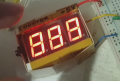
The problem is that only the Counter is seeing the fast speed. If I put osciloscope probe just goes High but no visible oscilations. Also the fv caounter is not seeing anything.
I tested with multiple components and indeed for some values my numeric Counter is giving the expected 888 and for other values, just stops. THis was good enough for me to figure out the proper componets values.
I tried with a third NAND gate output, with an opamp set as buffer (unity 0 gain), and with a 4027 FF, to read something on their outputs with the osciloscope and NOTHING. But I got the numeric Counter reading. This tells me that the signal is extremely weak in amplitude. This is very weird for me, this signal not being possible to raise its amplitude....
This is all I got so far...
 

Thread Starter

q12x

Joined Sep 25, 2015
2,245
describe to me what is my numerical clock seeing and the osciloscope not seeing?
This is the PIN input of my "numerical" Clock that is so sensitive. Its a CLK pin from a 4033 IC with 100k to GND (pull - low). So it's definetly getting the High spikes or whatever waveform (if any) .
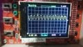
. 1700483035117.png. 1700482415175.jpg. . . .
 

MrChips

Joined Oct 2, 2009
35,279
Don’t connect any probe directly to the oscillator.
Probe a signal derived from the circuit, i.e. use an inverter, logic gate, flip-flop, counter, etc. A multi-stage counter such as CD4040 would be a good idea.
 

Thread Starter

q12x

Joined Sep 25, 2015
2,245
After speaking with an UK friend, he give me a genious idea to convert my already build counter, into a dividing signal for my dicky osciloscope. Genius and I also want to share it here with you.
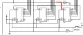
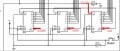
Internal cct of my fv Counter you see in the picture with RED digits:
Screenshot_1.jpg
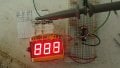
And in reality:
20231121_072314.jpg20231121_072315.jpg20231121_072324.jpg

BUT.... there are some issues.
1 - the fact remains that the crystal signal is still very weak.
2 - the results Im seeing here are from the 4033 IC, and not from the crystal signal directly. So Im seeing some indirect waveform now. But is fine, it tells me it is catching some sort of oscilations. This is progress !
3 - when I take out the crystal, the waveform remains almost the same, and most importantly, oscilating ! Almost means that it is a bit larger, and when Im inserting the crystal back, it is shrinking - but a little bit. THis is probably because of the capacitor in the circuit and most probably from some self-oscilation of the 7400 IC. THis is bad, because...I can't be completly sure which is the crystal oscilation and which is self-oscilation.... BUT... I decided to make a leap of faith and concentrate on the crystal for now.
This is a bit of progress in making these 32kHz crystals work with my circuits - this is the real goal here !
 

Thread Starter

q12x

Joined Sep 25, 2015
2,245
I have a question !
I have a list of osciloscopes put aside for more than 15 years, and the cheapest of them all, the price winner, is FNIRSI 1014D.
1700551216264.png
(It will be very cool if you have this specific model and speak from experience. Also provide pictures in future questions.)
Im only curious if this particular model can read crystal oscillators and at what fv range? 4MHz-40MHz like my dicky DL4YHF Frequency Counter? or 0-200kHz like my other dicky DSO138 Digital Oscilloscope?
- Another helpful question, what is the fv range of your osciloscopes that you usually use? (put it's full name). More important, yours, can directly measure a crystal ? At what ranges?
- Another helpful question, what is the fv range of a --general-- osciloscope that you know in general ? Like a global information that everyone should know.
I did read FNIRSI 1014D datasheet but mostly explains button functions and screen markings. Nothing helping answering this specific question I have here. Feel free to look inside it, maybe you will see something I escape. This datasheet is image based, not text based so I/You can't search for specific words in it. Shameless made ! Ok.
Thank you.
 

Thread Starter

q12x

Joined Sep 25, 2015
2,245
You might have destroyed your crystals by over driving them with your failed circuits.
check my #28 and #29 posts and you will understand that my crystals are fine. Also check if your osciloscope can read directly a cryystal, or if you need a crystal driver to read the fv with osciloscope.
 

Jon Chandler

Joined Jun 12, 2008
1,658
Also check if your osciloscope can read directly a cryystal, or if you need a crystal driver to read the fv with osciloscope.
A crystal oscillates at its resonant frequency when it's excited by a driver circuit. No oscilloscope will provide a drive signal.

A 4 wire crystal clock is an entirely different beast. You provide DC power to it and an integral driver circuit provides the needed excitation.


sv
 

BobTPH

Joined Jun 5, 2013
11,666
I don’t know what an fv is.

My scope can scope a MHz crystal using the 10X setting in the probe. At 1X it stops oscillation. Not sure about 32KHz. I think it had trouble with that even at 10X.

when I take out the crystal, the waveform remains almost the same
How does this prove the crystal is good? It suggests the opposite to me.
 

Thread Starter

q12x

Joined Sep 25, 2015
2,245
A crystal oscillates at its resonant frequency when it's excited by a driver circuit. No oscilloscope will provide a drive signal.
I see. I also suspect it but I asked anyway. So basically, you need a Xtal, a driver for the Xtal, and with the osciloscope read what the driver outputs. Very good answer. Thanks.
A 4 wire crystal clock is an entirely different beast. You provide DC power to it and an integral driver circuit provides the needed excitation.
I have a few 4pin scrapped crystals and I never knew how to drive or connect one. So you say it is having an internal integrated driver inside? Thats VERY convenient !!! I didnt know this detail.
Like this and I also see some SMD versions with 4pads instead of legs.
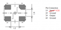
1700567174257.png1700567899653.png pin 1is OE = Output Enable/disable. Very interesting configuration !
But the most common is this with 2 gnd pins:
1700568002388.png
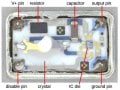
This img helped a bit more - I see it has an IC inside !!! Very interesting !
1700568042925.jpeg
Very good that you bring up this detail !
 
Last edited:

Thread Starter

q12x

Joined Sep 25, 2015
2,245
I don’t know what an fv is.
fv = frequency
My scope can scope a MHz crystal using the 10X setting in the probe. At 1X it stops oscillation. Not sure about 32KHz. I think it had trouble with that even at 10X.
So you are connecting the probes of the osciloscope directly to the crystal legs and the scope is reading it?
With no driver in between the Xtal and the probes? Thats interesting !
"
when I take out the crystal, the waveform remains almost the same
"
How does this prove the crystal is good? It suggests the opposite to me.
Yes... that is an unfortunate result and I am thinking on it how to solve it.... it might be the osc from the cap in the circuit that is stabilizing, but when the crystal is inserted, the fv is corrected. It is my hope and my impression. I hope Im right. If not, Im screwed. But I have a test in plan so will see later how things are evolving.
 

Janis59

Joined Aug 21, 2017
1,894
Crystalls have a large range different Q-factor. Those with a small demands larger oscilator S value and those having large will work on any generator. Thus, reccomend to measure it before using by appropriate VNA instrument.
 

BobTPH

Joined Jun 5, 2013
11,666
So you are connecting the probes of the osciloscope directly to the crystal legs and the scope is reading it?
With no driver in between the Xtal and the probes? Thats interesting !
No! I place the probes on gnd and output side of the xtal in an oscillator circuit. You will get nothing if you simply probe the unconnected xtal. Just like you would no a resistor.
 

Thread Starter

q12x

Joined Sep 25, 2015
2,245
No! I place the probes on gnd and output side of the xtal in an oscillator circuit. You will get nothing if you simply probe the unconnected xtal. Just like you would no a resistor.
ah so you are using a crystal driver then. Ok. THanks.
So for MHz Xtals your scope is reading them (after driver) and also set on x10. But not on x1.
My dicky osciloscope is 0-200kHz range, and the probe was all the time set to x10. So my reading is 3kHz actually on the screen. But is not showing it. Hmmm. Must be a voltage amplitude problem maybe - like being in the mV oscilations and the reading gets lost in the general noise that my osciloscope is constantly reading when nothing happens.
 

MrChips

Joined Oct 2, 2009
35,279
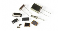
To summarize what has been said, there are different quartz crystals packaging.

1700579143510.png

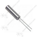
This is a common 32768Hz quartz crystal package.
1700579207215.png


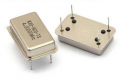
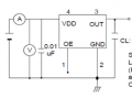
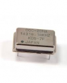
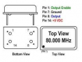
This is a common 4-pin quartz crystal oscillator module for thru-hole mounting.
1700579403737.png
Typically,
pin-14 = Vcc = +5VDC
pin-7 = GND
pin-8 = 5V oscillator output

Why are there four pins when only three pins are needed? There are four pins for secure mounting on the PCB. Sometimes the 4th pin is used for another function. For example, the 4th pin could output a lower frequency, i.e. the fundamental divided by a power of 2. For example, pin-8 could be 8MHz while pin-1 is 500kHz output.

1700579516508.png

What is in a quartz crystal oscillator module?
The essential components are:
  1. quartz crystal
  2. oscillator circuit
  3. driver circuit
  4. optional divide-by-N counter or enable logic

A quartz crystal on its own will not oscillate. You cannot measure the frequency with an oscilloscope.
The quartz crystal needs an oscillator circuit for sustained oscillation. The loading capacitance is very critical for proper resonance. In most cases, you cannot measure the frequency directly with an oscilloscope or frequency meter. That is because the measuring instrument will load down the circuit and the crystal will stop oscillating. You need to probe the circuit after the oscillator has been buffered or processed through high impedance buffers and digital counters.

Some oscillator circuits will oscillate without the quartz crystal. Adding the quartz crystal will lock the oscillator into the crystal's resonance frequency.

Quartz crystals intended for accurate time-keeping purpose are intentionally cut to resonate at a few ppm higher than the nominal frequency. For example, a 32768Hz clock crystal might resonate at 32770Hz. The circuit designer would install a trimmer capacitor in order to bring the resonant frequency down to the exact desired frequency. This is done through proper calibration against accurate time and frequency standards.

32768Hz clock crystals can be destroyed if they are over-driven. This is the purpose of the 200k-500kΩ resistance in series with the crystal to limit the drive on the crystal.

Hope this helps.
 
Thread starter Similar threads Forum Replies Date
ronsimpson General Electronics Chat 5
schmitt trigger Off-Topic 2
Top