Facebook
 Google
 GitHub
 Linkedin
I've been using for a while now the HCPL-9030 as 5VDC to 90VDC isolators (they work through magnetic coupling, and not optically) to drive the inputs of an IR2101, which in turn are being used to drive the gates of 4 nFets in an h-bridge.
I like those isolators because they perform quite well at high frequencies. Problem is, that I found that they're a bit fragile and susceptible to small voltage spikes and will occasionally malfunction. Even worse, they will latch and might cause a catastrophic short circuit between the high and low nFets on the same side of the bridge... I speak from personal experience on this (more on that later, on a different thread)
After doing some searching, I found that the 6N137 optoisolators might be just the ticket. They're capable of handling high frequencies, just as I want. But the problem is that they have an open collector output, and they work using inverted logic (which is a characteristic of all optos that I'm familiar with). And therefore are turned on by default when they're powered up, and will only turn off after current starts flowing through their internal LED.
Question, is there a way to connect these optos in such a way that they will always be off by default when they're powered up on the isolated side, but their internal LED is not yet energized? These chips feature an enable pin, but it also works using inverted logic, and I can't fathom how I could take advantage of that.
To be clear: I want all four nFets to remain off after power is applied to their drivers and to the isolated side of the optos, but not yet to their LEDs. Or better yet, it would be ideal if the isolator's output could be inverted without a glitch being suffered during power up.
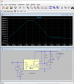
Attachments
-
1.2 MB Views: 7
Last edited: