Extending RF Range on AC304-02 Modules for Pergola Louver Control

Thread Starter

jmbinette

Joined Mar 17, 2021
9
Hi to all,

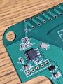
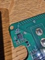
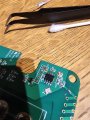
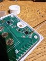
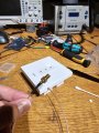
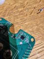
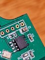
I am undertaking a project to extend the remote control range for pergola louvers controlled by AC304-02 modules, which are generic roller shutter controllers operating at 433.92 MHz. These modules utilize a CMT2210LB RF chip and are paired with a standard Dooya 15-channel remote. The original design includes a planar helical antenna etched directly onto the PCB.

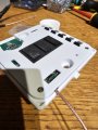
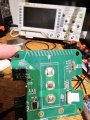
I am considering cutting the trace to this antenna and soldering an SMA connector for attaching an external antenna to improve the range. For those interested, here's a look at the module: AC304 Module Details

I have a few questions:

Would replacing the built-in antenna with an external one effectively extend the control range?
Does anyone have recommendations on where to solder the signal and ground for the SMA connector on this specific PCB?
Are there any potential risks or important considerations I should be aware of with this type of modification?
Alternatively, I'm considering the possibility of using an RF repeater. Does anyone have experience with RF repeaters for 433.92 MHz systems?

I've got a test unit specifically for this purpose, so I'm ready to experiment based on your suggestions.

Any insights, especially from those familiar with RF systems or the CMT2210LB chip, would be greatly appreciated.

Thanks!
 

Attachments

Ya’akov

Joined Jan 27, 2019
9,277
Welcome to AAC.

Your proposed modification may or may not “work” but it will certainly be illegal. Making changes to the antenna will destroy the devices regulatory compliance which is based on the module and antenna (system).

The saving grace of your proposal is you only intend to modify the receiver. This is still counter to regulations but is much less likely to be a source if interference then adding to the ERP (Effective Radiated Power) of a transmitter. The challenge you will encounter is ensuring a match from feedline to IC pin.

The datasheet for the CMT2210 glosses over antenna details but provides enough information for your purposes. It shows a typical application schematic, including the matching network for the input to the LNA—

1714902801312.png
—and mentions 50Ω input impedance in passing (no surprise there). The trouble for you is the potential that the existing matching network simply won’t operate properly with an “improved” antenna, and the receiver will end up even more deaf that it already is. Maintaining that 50Ω will range from important to critical depending on the chip‘s internals (I have no insight on this).

As far as connectors go, you will be far better off trying to fit a IPEX type connector than an SMA. You can get pigtails that go from IPEX to SMA female to attach an SMA terminated antenna which also provides a way to mount the antenna. Keep the feedline (from IPEX to SMA) as short as possible.

1714903348214.png
As far as antennas go, there is another challenge: many of the antennas sold claiming to be resonant on a particular band are—not. They are either relabeled from some other band and passed off, or they are not really resonant on any useful band. This means you either have to be able to measure the SWR of the antenna, or you will have to “cut and try” (or in this case, maybe more like “try and cut, then chuck in the bin”.)

1714903919532.png
a typical example candidate not a recommendation

The right way to do this would be with a VNA (Vector Network Analyzer) and you can get an amazingly effective instrument in the form of the NanoVNA. If you intend to do RF work in the future, it is a gem and not a bank breaking proposition. It will allow you to vet antennas by showing their actual resonance, among other useful things. Well, well worth both the cost and time spent learning (lots of direct tutorials showing particular tasks to be found on YouTube).

1714904192428.png

As far as repeaters go, I suggest you instead consider the one of the various IoT gateways that can be used with a phone app. They generally learn the radio codes, then use them to interface between the app and the device under control.

They can be quite cheap and you can use more than one. Two examples are this Sonoff bridge that works with the eWeLink ecosystem (it’s very small, about 60mm square/20mm deep)

1714900955055.png
and this device (which I know less about) that works with the Tuya ecosystem and is nearly identical in overall size to the Sonoff.

1714901591652.png

Both offer connectivity to Alexa and Google home through their respective ecosystems. Sonoff is a well established company with a solid IoT platform. The Tuya IoT world is very extensive because they offer a relatively cheap and painless way for a manufacturer to add IoT features to a product, including the Tuya app and cloud.

The problem with attempting a purely RF solution is there is no regulatory basis for it. While your receiver centered proposal is most likely “safe”, any approach you take will be in contravention of the regulations. The high channel loading of the 433MHz ISM band (only getting worse) means interference with the operation of devices in other people’s homes becomes more and more likely for any modified device.

There is a delicate balance the regulators attempt to walk in unlicensed bands and modifying the equipment to have a better receive antenna is going to be invisible to neighbors (in all probability) while increasing the ERP of the transmitter (the ”easier” path) has real potential for harmful interference.

Good luck with your project.
 

Thread Starter

jmbinette

Joined Mar 17, 2021
9
Thank you for the detailed insights and the caution regarding regulatory compliance and potential interference. I understand the importance of maintaining the system within legal limits and appreciate your comprehensive explanation.

To clarify, my goal isn’t necessarily to increase the transmitter's power but rather to improve signal accessibility and reliability, especially given the positioning challenges. The module is located under a patio, and the remote is used from a first-floor level. My thought was that relocating the antenna—perhaps moving it from being directly on the PCB to a more strategic location nearby—might help overcome some of the signal obstructions caused by physical barriers.

Considering this, I have a few follow-up questions:

  1. Would relocating the antenna to a different position while maintaining the original design (not increasing ERP) help in this scenario?
  2. If an antenna move is feasible, what type of antenna would you recommend for this specific application? I am looking for options that are reliable and readily available from well-known vendors.
  3. Could you suggest any vendors or specific antenna models that have proven effective in similar use cases?
 

Ya’akov

Joined Jan 27, 2019
9,277
Thank you for the detailed insights and the caution regarding regulatory compliance and potential interference. I understand the importance of maintaining the system within legal limits and appreciate your comprehensive explanation.

To clarify, my goal isn’t necessarily to increase the transmitter's power but rather to improve signal accessibility and reliability, especially given the positioning challenges. The module is located under a patio, and the remote is used from a first-floor level. My thought was that relocating the antenna—perhaps moving it from being directly on the PCB to a more strategic location nearby—might help overcome some of the signal obstructions caused by physical barriers.

Considering this, I have a few follow-up questions:

  1. Would relocating the antenna to a different position while maintaining the original design (not increasing ERP) help in this scenario?
  2. If an antenna move is feasible, what type of antenna would you recommend for this specific application? I am looking for options that are reliable and readily available from well-known vendors.
  3. Could you suggest any vendors or specific antenna models that have proven effective in similar use cases?
I did suggest that you put an IPEX connector on the board and use an IPEX to SMA female pigtail to remote mount it on the housing. It could make a difference, there are too many variables to know for sure. It’s worth a try if you want to go to the trouble. As far as antenna, I suggested you get a NanoVNA and check the candidates.
 

Thread Starter

jmbinette

Joined Mar 17, 2021
9
I did suggest that you put an IPEX connector on the board and use an IPEX to SMA female pigtail to remote mount it on the housing. It could make a difference, there are too many variables to know for sure. It’s worth a try if you want to go to the trouble. As far as antenna, I suggested you get a NanoVNA and check the candidates.
Thank you, sorry for missing this important part.

I just ordered a NanoVNA h4 and will try to characterize the existing antenna and search for potential candidates

Thanks again
 

Ya’akov

Joined Jan 27, 2019
9,277
Thank you, sorry for missing this important part.

I just ordered a NanoVNA h4 and will try to characterize the existing antenna and search for potential candidates

Thanks again
You are most welcome, please follow up with any questions you might have.

Also, have fun with the NanoVNA, it’s quite a tool—there’s been nothing like it before, “real” VNAs are extremely expensive and the NanoVNA puts unprecedented abilities in the hands of even a casual hobbyist. The investment you have to make is in learning.
 

Thread Starter

jmbinette

Joined Mar 17, 2021
9
You are most welcome, please follow up with any questions you might have.

Also, have fun with the NanoVNA, it’s quite a tool—there’s been nothing like it before, “real” VNAs are extremely expensive and the NanoVNA puts unprecedented abilities in the hands of even a casual hobbyist. The investment you have to make is in learning.
Hi again,

I will receive my NanoVNA tommorow along with the connectors. In the meantime, I watched some videos like you suggested and prepped the pcb to test another antenna and/or characterize the existing.

I tried to reproduce the schematic to the best of my knowledge.

I cut the pcb trace that goes to the existing antenna and exposed 2 temporary soldering pads.

If I understand right, I will be able to read the pcb antenna impedance at 433Mhz with the VNA ? I would solder the jumper and measure at pin 5 ?

After that, I would remove the jumper, install the new antenna and repeat the process?

Any help at this point in preparation of my tests will be appreciated !

I included some pictures.

Thanks again !
 

Attachments

Ya’akov

Joined Jan 27, 2019
9,277
You can safely assume the antenna and feedline (traces) are 50Ω. The measurement of interested is the SWR of any candi date antenna at 433.92MHz. You might as well test the on-board antenna, if it is poorly matched, it could be part of your problem.

However, you can’t use jumpers, you will have to connect a 50Ω coaxial cable (short as possible, to the antenna and the closest possible ground.any wires you add become part of the antenna and will make measurement impossible.

I’ll try to write more tomorrow.
 

Thread Starter

jmbinette

Joined Mar 17, 2021
9
You can safely assume the antenna and feedline (traces) are 50Ω. The measurement of interested is the SWR of any candi date antenna at 433.92MHz. You might as well test the on-board antenna, if it is poorly matched, it could be part of your problem.

However, you can’t use jumpers, you will have to connect a 50Ω coaxial cable (short as possible, to the antenna and the closest possible ground.any wires you add become part of the antenna and will make measurement impossible.

I’ll try to write more tomorrow.
Hi,

Here is an update of my tests.

I received my NanoVNA tonight, I must say this a really nice piece of hardware for the price !

I calibrated the VNA for a stimulus of 400 to 450Mhz. Then I configured a trave for LOGPHASE and connected my unsolved SMA pigtail. I played with the delay values until I reached 0deg. (About 852ps).

I used this delay on the graph to compensate my pigtail and calibrate the reference plan of my pcb.

Then I soldered ground and antenna signal on the pcb.

I will need some help to analyze the results. From what I see, I have a SWR of 1.5 at 433Mhz and 1.2 at 430Mhz so would it be true to say than the pcb antenna is not perfectly tuned ?

Does the SMITH trace gives me the antenna impedance ? Looks like I am around 50.

Also, now I should test an External antenna and try to get better or equivalent results ?

Also, I would like to know where I should solder the signal of the external antenna. After the Caps and Inductance or directly to pin 5?

Thanks again for your help. I feel like really learning useful skills!
 

Attachments

Thread Starter

jmbinette

Joined Mar 17, 2021
9
Hi,

Here is an update of my tests.

I received my NanoVNA tonight, I must say this a really nice piece of hardware for the price !

I calibrated the VNA for a stimulus of 400 to 450Mhz. Then I configured a trave for LOGPHASE and connected my unsolved SMA pigtail. I played with the delay values until I reached 0deg. (About 852ps).

I used this delay on the graph to compensate my pigtail and calibrate the reference plan of my pcb.

Then I soldered ground and antenna signal on the pcb.

I will need some help to analyze the results. From what I see, I have a SWR of 1.5 at 433Mhz and 1.2 at 430Mhz so would it be true to say than the pcb antenna is not perfectly tuned ?

Does the SMITH trace gives me the antenna impedance ? Looks like I am around 50.

Also, now I should test an External antenna and try to get better or equivalent results ?

Also, I would like to know where I should solder the signal of the external antenna. After the Caps and Inductance or directly to pin 5?

Thanks again for your help. I feel like really learning useful skills!
@Ya’akov hope you are doing well

Here's another update.

I desoldered L2 and C10
Scratched a pad on the ground plane to receive the ipex connector and soldered the signal directly to pin 5

Now I guess I could try a 433.92Mhz antenna with SMA connector. Should arrive this weekend.

Let me know your thoughts

Thanks !
 

Attachments

Ya’akov

Joined Jan 27, 2019
9,277
Hello. That looks like excellent progress!

If you want to try something before you get the antenna, cut a ¼λ antenna* from some stiff wire that will fit into the SMA connector. Cut a similar (slightly longer piece and wrap it around the threaded part and ”down” 45° “out” from parallel to the wire as a ground radial.

Use the NanoVNA to check that you have a reasonable SWR (≤1.5:1 at 443.92MHz) with the cut pieces using one of the included SMA → SMA jumpers and the female → female SMA barrel. Make the radiator at least a 3 or 4mm too long after accounting for the part that will fit into the SMA‘s pin socket. This way you will latitude to tune by removing just a little bit at a time (~.5mm).

(*Roughly 164.2mm for the radiator, and 183.9mm for the part of the ground radial that isn’t wrapped around the connector body—3 radials, 120° apart at 45° angles is ideal)

This might give you some idea of your success, but don’t take it as a failure if it doesn’t work well—there are a lot of possible confounding factors.

Otherwise things look quite good. Sorry for the long time in responding and the brevity—thing are very busy here just now. But from what I can see it looks on track. Of course, keep me updated!
 

Thread Starter

jmbinette

Joined Mar 17, 2021
9
Hello. That looks like excellent progress!

If you want to try something before you get the antenna, cut a ¼λ antenna* from some stiff wire that will fit into the SMA connector. Cut a similar (slightly longer piece and wrap it around the threaded part and ”down” 45° “out” from parallel to the wire as a ground radial.

Use the NanoVNA to check that you have a reasonable SWR (≤1.5:1 at 443.92MHz) with the cut pieces using one of the included SMA → SMA jumpers and the female → female SMA barrel. Make the radiator at least a 3 or 4mm too long after accounting for the part that will fit into the SMA‘s pin socket. This way you will latitude to tune by removing just a little bit at a time (~.5mm).

(*Roughly 164.2mm for the radiator, and 183.9mm for the part of the ground radial that isn’t wrapped around the connector body—3 radials, 120° apart at 45° angles is ideal)

This might give you some idea of your success, but don’t take it as a failure if it doesn’t work well—there are a lot of possible confounding factors.

Otherwise things look quite good. Sorry for the long time in responding and the brevity—thing are very busy here just now. But from what I can see it looks on track. Of course, keep me updated!
Good morning,

I wanted to share an update on my project.

I received the antennas from Amazon and analyzing them with NanoVNA, found out they were not that good !
So disassembled them and recoiled a longer antenna, tuned it with the analyzer.

Now I would need to make deeper tests but I would say the reception is at least 25% better now !

Thanks again ! Learned a lot in the process
 

Attachments

Top