Expression for Current in a Small Signal Differential Amplifier

Thread Starter

HunterDX77M

Joined Sep 28, 2011
104
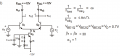
I have the diagram attached for a small signal model of a differential amplifier that my professor gave me. I am having a little trouble understanding where he got the expression for the current ib2.

According to his notes, it says that when source e2 is 0 V (that is, shorted to ground), the expression for the current is

\(i_{b2} = \frac{-e_1}{2 \times h_{ie}}\)

I've been staring at this for a while now trying to understand his logic and am stumped. How did he get this expression? What loop do you have to go through? Thanks in advance for any help.
 

Attachments

Last edited:

LvW

Joined Jun 13, 2013
1,759
I suppose, it is obvious that the corresponding circuit is the classical two-transistor differential pair with an ohmic resistor Ro in the common emitter path.

*However, the mentioned expression R=Ro(1+beta) applies only if one of the signal sources is set to zero volts (in the case under discussion e2=0).
* Now - it can be assumed that the value of R is much larger than hie since the value of hie typically is in the lower kOhm range.
* In this case, it is obvious that ib2=-e1/2*hie.
* This result confirms the known fact that the signal input resistance of a common-collector-common base combination has an input resistance of 2*hie (identical transistor parameters assumed).
 
Last edited:

Thread Starter

HunterDX77M

Joined Sep 28, 2011
104
It would help to have the schematic of the circuit for which this is the small signal model.
As requested, here is the original circuit. My question wasn't so much an analysis question as it was an algebra question, which is why I didn't include it originally and went straight to the small signal model.
 

Attachments

Thread Starter

HunterDX77M

Joined Sep 28, 2011
104
I suppose, it is obvious that the corresponding circuit is the classical two-transistor differential pair with an ohmic resistor Ro in the common emitter path.

*However, the mentioned expression R=Ro(1+beta) applies only if one of the signal sources is set to zero volts (in the case under discussion e2=0).
* Now - it can be assumed that the value of R is much larger than hie since the value of hie typically is in the lower kOhm range.
* In this case, it is obvious that ib2=-e1/2*hie.
* This result confirms the known fact that the signal input resistance of a common-collector-common base combination has an input resistance of 2*hie (identical transistor parameters assumed).
Thank you for your response; it makes a lot of sense. My professor wasn't clear that he took R >> hie, which is why I wasn't sure where he got that expression from. It is now obvious that since you effectively have 2hie there, it is basically a voltage divider cutting e1 in half.
 

LvW

Joined Jun 13, 2013
1,759
Hunter, because you have mentioned the expression R=Ro(1+beta) I have assumed an ohmic emitter resistance. Now - with respect to your circuit diagram - the value of Ro seems to be the dynamic internal resistance of the BJT current source in the common emitter path.
Thus, the mentioned assumption (R>>hie) is fullfilled even better.
 
Top