Equations power delivered by a capacitor

Thread Starter

ashokraj

Joined Feb 1, 2018
151
Hi,
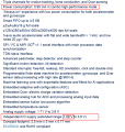
I would like to know how much time a capacitor can deliver the power to the system. Please consider the following: I have kept the following decoupling capacitors across the power rail of a sensor. I would like to know if the source(VDD_2V4_Accel) is turned for some time, how many seconds/milli seconds can these C1,C9,C8 can deliver the power ? what are the equations I should know to calculate it?

1719909877139.png
 

MrChips

Joined Oct 2, 2009
34,629
The simple answer is,
time constant = R x C
where R is the load.

The voltage on the capacitor will drop by 63% (to 37% of the initial value).
For an approximation, you can use a simple linear extrapolation for smaller voltage drop.

For example, a 39% voltage drop (to 61% of initial voltage) will take approx. RC/2 seconds where,
R is load in ohms,
C is capacitance in farads

1719928919931.png

Half time constant = RC/2 μs, where C is in μF.
For R = 250 Ω and C = 4 μF
RC/2 = 500 μs = 0.5 ms

A quarter of the time constant, RC/4, is about 22% voltage drop.
10% voltage drop occurs after RC/10.

Here are some approximate time constant vs voltage drop .

Time Constant -> % Voltage Drop
0.01 RC -> 1%
0.02 RC -> 2%
0.05 RC -> 5%
0.10 RC -> 10%
0.20 RC -> 18%
0.25 RC -> 22%
0.33 RC -> 28%
0.40 RC -> 33%
0.50 RC -> 40%
0.70 RC -> 50%
1.00 RC -> 63%
 

Thread Starter

ashokraj

Joined Feb 1, 2018
151
I
The simple answer is,
time constant = R x C
where R is the load.

The voltage on the capacitor will drop by 63% (to 37% of the initial value).
For an approximation, you can use a simple linear extrapolation for smaller voltage drop.

For example, a 39% voltage drop (to 61% of initial voltage) will take approx. RC/2 seconds where,
R is load in ohms,
C is capacitance in farads

View attachment 325986

Half time constant = RC/2 μs, where C is in μF.
For R = 250 Ω and C = 4 μF
RC/2 = 500 μs = 0.5 ms

A quarter of the time constant, RC/4, is about 22% voltage drop.
10% voltage drop occurs after RC/10.

Here are some approximate time constant vs voltage drop .

Time Constant -> % Voltage Drop
0.01 RC -> 1%
0.02 RC -> 2%
0.05 RC -> 5%
0.10 RC -> 10%
0.20 RC -> 18%
0.25 RC -> 22%
0.33 RC -> 28%
0.40 RC -> 33%
0.50 RC -> 40%
0.70 RC -> 50%
1.00 RC -> 63%
would like to understand how R is considered as 250 ohms?
 

WBahn

Joined Mar 31, 2012
32,706
Whatis the reason for taking 250 ohm as R1?where can I see that in datasheet? and why the V reference (V1) is 1.08V?
Something had to be picked and we are not mind readers.

YOU need to determine how much current your load requires and at what voltage it stops functioning acceptably.
 

ericgibbs

Joined Jan 29, 2010
21,395
Whatis the reason for taking 250 ohm as R1?where can I see that in datasheet? and why the V reference (V1) is 1.08V?
Hi ash,
I made an approximation based on these figures from the d/s.
The 1.08v is the quote minimum operating voltage
E
 

Attachments

Top