Equalizer and Crossover Circuit

Thread Starter

Zohar

Joined Nov 19, 2015
70
Hi

I was reading today about building a simple Equalizer circuit, and found this wonderful and simple PDF:
www2.ece.ohio-state.edu/~anderson/Outreachfiles/AudioEqualizer.pdf


They explain there about Low-Pass Filter, High-Pass Filter, and a combination of the two - Band-Pass Filter.

The result circuit that was built there, which is a simple 3-Band Equalizer, looks like this:


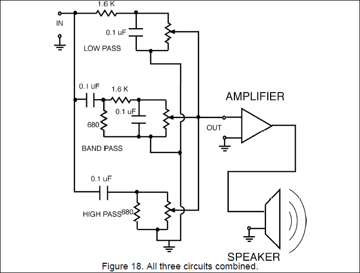
So far everything is OK.

As can be seen, this circuit is made of Resistors and Capacitors.


Now, sometime ago a person told me, that to build a Low-Pass/High-Pass filter, I need to use Capacitors and Inductors.
He told me to google "Crossover", in order to see the circuit,
and indeed the circuit for CrossOver is LC and not RC...

For example:


http://www.diyaudioandvideo.com/Tutorial/DesignBuildCrossover/


As can be seen, the circuits here are completely made of Capacitors and Inductors, and no Resistors..


So my question:
For building a simple equalizer,
which of the 2 ways is better:
The first (RC),
or the second (LC, like the Crossover example)?


Thank you
 

crutschow

Joined Mar 14, 2008
34,469
RC is fine for a tone or frequency control circuit in front of the amplifier (inductors are not commonly used for that application).
LC's are used when the filter is after the amplifier and drives a (mostly) resistive speaker load since resistors in that case would waste too much power.
 

Thread Starter

Zohar

Joined Nov 19, 2015
70
So the main reason to choose between RC and LC is whether the circuit is Before or After the amplifier?
OK, great then.

In my case I am building a simple Equalizer, and it is before the Amplifier, so I stick with the RC Circuit.


BTW,
regarding the Capacitors,
there are several different Capacitor types,
for example see the type list sold in Tayda Electronics:


http://taydaelectronics.com/

So my question:
When building an Analog Circuit that deals with Audio,
Is a certain type of Capacitors better for the purpose, over other types?
 

MrChips

Joined Oct 2, 2009
30,824
So the main reason to choose between RC and LC is whether the circuit is Before or After the amplifier?
It is a matter of impedance matching.

Inputs of amplifiers have relatively high input impedance, 1k-100kΩ, maybe.
Loudspeakers have very low impedance, 2-8Ω typical.
An LC filter is better suited for low impedance loads, hence better for speaker crossovers.
Conversely, the low impedance of an LC filter does not match the high impedance of the amplifier inputs. With an RC filter, you can select a relatively large value of R and hence manage with smaller values of C for the same roll-off frequency.

Secondly, an RC filter is a 1st-order filter, with a gain of -3dB/octave in the attenuation band.
An LC filter is a 2nd-order filter, with a gain of -6dB/octave, i.e., twice the bang for the buck.

For RC filters, where the value of C is low (less than1μF), you want to use capacitors fabricated from stable dielectrics such as polyester or mylar.
For larger values of C as used in cross-over networks, you have to make sure that the capacitor is non-polar.
 

Thread Starter

Zohar

Joined Nov 19, 2015
70
Great, thank you for all this.

Another question regarding it please:

In the Audio Equalizer PDF, they give a formula for calculating the frequency that is affected by the R and the C.


I tried calculating myself the result, using their values (R=680Ω, C=0.2μF),
and the result I get is not 2500 like they got,
but instead 1170..

Is there a mistake in my calculation, or there is a small mistake in the PDF?
 

Thread Starter

Zohar

Joined Nov 19, 2015
70
OK Thank you for verifying it..

I sent now an email to the creator of the PDF,
hopefully she will fix it, so other people who read it won't wonder what is wrong with their calculation..


BTW
I found now another circuit which is slightly similar to the first circuit (RC) that I brought here,
yet different from it.

Please see this circuit:

:

Unlike the first circuit which was RC, CR, and RC+CR (for the band-pass),
in this circuit, it is RCR, in all 3 parts of it..

So it seems there are 2 options to implement an Equalizer circuit..
Which of them is better?
 

Thread Starter

Zohar

Joined Nov 19, 2015
70
On one hand, the second circuit has more consistency,
because for every part (band), the sub-circuit is RCR, and the Potentiometer is always parallel to the C.

However there is one thing there that I do not completely understand..
The result that comes out of the Potentiometer, sometimes goes thru a Resistor, and sometimes thru a Capacitor..
See it here:


crutschow

Joined Mar 14, 2008
34,469
The result that comes out of the Potentiometer, sometimes goes thru a Resistor, and sometimes thru a Capacitor..
The bass control uses a resistor so the low frequency response goes to DC.

Looking through my simulations I found your second circuit.
The main difference is mine uses two power supplies and yours is biased for one.
Also the tone controls are in a different order and it has a different opamp.

Here's my LTspice simulation results for 0%, 50%, and 100% position of the pot wipers (W, W1, and W2):

P.S. You forgot to connect the left end of R4 in your schematic.

upload_2016-11-12_0-50-18.png
 

Thread Starter

Zohar

Joined Nov 19, 2015
70
P.S. You forgot to connect the left end of R4 in your schematic.
Neither one of the 3 circuits are my design..
They are all downloaded from the internet, after searching with google..
And yes I saw too that they forgot to connect the middle sub-circuit..

I think that in terms of simplicity, the first circuit preferable: smaller, and less components.


BTW, If I implement the first circuit, with just the Low-Pass and the High-Pass parts,
without the Band-Pass part,
so I actually achieve a control over the Bass and Treble,
What are the 2 recommended frequencies for that?
(F1 for the Low-Pass, and F2 for the High-Pass)
 

crutschow

Joined Mar 14, 2008
34,469
.........
BTW, If I implement the first circuit, with just the Low-Pass and the High-Pass parts,
without the Band-Pass part,
so I actually achieve a control over the Bass and Treble,
What are the 2 recommended frequencies for that?
(F1 for the Low-Pass, and F2 for the High-Pass)
I don't know what the recommended frequencies for the bass and treble rolloff are.
The frequencies shown are probably good.
You can always change them if they don't seem to work well in your system.
Edit: I just realized you have to also implement the Band-Pass part.
It provides the pathway for the mid frequency signals to the output.

But I recommend you build the second circuit.
The first has obviously deficiencies, such as, if any pot is turned all the way to the bottom (ground) it will short out the input signal.
I don't think that circuit has every been built, it's just a paper design.
 
Last edited:
Top