Equalization & Ringing for a Square Wave Signal in VLC

Thread Starter

Boomin Perera

Joined Aug 27, 2015
6
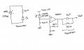
I am currently working on a VLC project to build a VLC receiver. I attached a schematic of the circuit I have designed. The circuit on the left is the transmitter sending a square signal at 1 MHz using the CREE RGB LED. I am receiving the signal at the other end using a OSRAM photo-diode and passing it through front end amplifier to amplify the received signal. Later its sent through a 1st order equalization circuit, to fix my distorted square wave signal. I am unsure whether my equalization circuit is correct since I do not see any change in the signal when I implement this circuit. I also experience a ringing (overshoot and oscillations to settle down) in the output waveform. Could you please help me understand the how I can equalize to get a better response to get a cleaner square wave and also to reduce the ringing in my circuit. Any response is much appreciated. Let me know if you need any more information.
 

Attachments

AnalogKid

Joined Aug 1, 2013
11,044
1. What is VLC?
2. Are you trying to recover the 1 MHz squarewave, of just detect that it is present?
3. The LED in the transmitter is in backwards.
4. Why use an RGB LED? Photodiodes respond to a narrow range of wavelengths.
5. Photodiode amplifiers usually run the diode as a current source driving the inverting input of the opamp. Search "photodiode amplifier circuit" for many examples.
6. Ringing in high speed circuits usually is due to grounding issues, like long leads or narrow traces. Also, it could be coming from the scope ground connection. On many scope probes the ground lead is 3 or 4 inches long and acts like a loop antenna.

ak
 

Thread Starter

Boomin Perera

Joined Aug 27, 2015
6
@Analog Kid -Thanks for the reply much appreciated.
1. Visible Light Communication
2. I am trying to recover it back
2. Sorry about that , its incorrect in the schematic
4. My project has been specified to using RGB LEDs (helps in WDM)
5. Thank you ill check on that , but in the design that part of the circuit works
6. I will look into that , thank you very much

Would you happen to know any analog circuits regarding channel equalization (to recover the square signal not been distorted)
 

ronv

Joined Nov 12, 2008
3,770
If your diodes are fast you shouldn't need any "equalization". You might try adding 50 ohms from the output to ground.
Do you have the circuit on a board with ground plane?
Good power supply decoupling?
Maybe a scope picture?
 

GopherT

Joined Nov 23, 2012
8,009
The ringing might be from the scope probes - the capacitance in the scope & probes. Try turning the probe to 10x and turning up the gain on the scope by 10x. Signal should be the same size on the screen. If the ringing goes away, it was because the output impedance of your test point was too high for the 1x setting on the oscilloscope probe.

EDIT: I just looked at your schematic, the capacitive load you are driving will cause the ringing. Put a buffer between your receiver op amp and you capacitive load. Ringing should go away.
 

Thread Starter

Boomin Perera

Joined Aug 27, 2015
6
If your diodes are fast you shouldn't need any "equalization". You might try adding 50 ohms from the output to ground.
Do you have the circuit on a board with ground plane?
Good power supply decoupling?
Maybe a scope picture?
-The stated bandwidth of the photo-diode is 90MHz . It should be fast enough
-I'll try it , but doesn't oscilloscope have 50 ohm resistor between probe and ground terminal
-I have it on a breadboard yes it has a ground plane connected to a voltage supply. Do you think using a PCB might help in this case?
-I am not too sure what does decoupling mean exactly , (does mean to use bypass capacitors)
-I'll upload my signal soon (but currently it looks like the bottom picture)
 

Attachments

Thread Starter

Boomin Perera

Joined Aug 27, 2015
6
Or use a transimpedance amplifier as in most circuits for the receive function. That configuration reduces the effects that diode capacitance has on rise and fall times and lends itself to frequency compensation more easily than the voltage follower.


http://electronicdesign.com/analog/whats-all-transimpedance-amplifier-stuff-anyhow-part-1
I tried using my photo-diode in this configuration , i wasn't able to get any output through this ( I wasn't too sure why)
 

Thread Starter

Boomin Perera

Joined Aug 27, 2015
6
The ringing might be from the scope probes - the capacitance in the scope & probes. Try turning the probe to 10x and turning up the gain on the scope by 10x. Signal should be the same size on the screen. If the ringing goes away, it was because the output impedance of your test point was too high for the 1x setting on the oscilloscope probe.

EDIT: I just looked at your schematic, the capacitive load you are driving will cause the ringing. Put a buffer between your receiver op amp and you capacitive load. Ringing should go away.
Thanks alot , I'll try your suggestions and get back to you. (I am using a BNC connector at the oscilloscope terminal do u know what the probe setting of that is (10x or 1x))
 

DickCappels

Joined Aug 21, 2008
10,179
@Boomin Perera , To use the opamp as a transimedance amplifier you need both a positive and negative power supply, or you ned to reference the non-inverting input of the opamp and the anode of the diode to a voltage above ground.
 
Top