The following circuit introduces a click noise into the audio signal (IN1, OUT1), whenever SW1 or SW2 is pressed. How can I eliminate/isolate that noise?
I just reread your post, I misunderstood the question. You want to eliminate the sound. This is likely going through the power supply, not the button itself. Filter it a bit tighter.
It is hard to say for sure, since I can't see the schematic the way it's set up (if it were a thumbnail the browser would autosize it), but I don't think I saw a filter cap on the +5V line? You might also isolate the digital and analog with a choke, but the capacitors come first.
Studing the schematic I have a little trouble seeing what your doing. I think I see a variable impedance on the output, is this used to vary gain or what? The multiplexer is connecting different resistors to the output, from what I'm seeing.
I'm wondering if the click is the sound of U4 and U6 switching?
I've used variation of those mux/demux chips to route audio around, but that doesn't seem to be what you're doing. I'm going with volume at the moment. I'm not thinking power supply any more.
It might be, but if the counter is at 7, the address lines on U4/U6 stay at logic 1. So it shouldn't switch. However, I still get the noise. The noise is more of a thump than a click. It is mid to low frequency.
Hi
By changing the switches you are changing the clock inputs to the 193 and that switches the 4051 which is connected to the audio line. The noise is probably due to the digital change in the circuit and is inherent in the design since that is what the switches were meant to do. The only way to see if it is a fault is to get a scope on the input and output of the 4051. It might show a switching spike that could be absorbed on the digital inputs of the 4051. Usually digital outputs are inhibited while they are being changed if used with audio circuits otherwise all the switching noise is sent directly to line.
Hope this helps.
How easy is it to try experiments on your board? My thought is to use a second +5 power supplies, completely isolated from the first, to power U4/U6. This should prove whether it is the power supply or not, and offer a clue how to fix the problem.
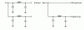
If it is the power supply, and I am loath to commit at this point, you need to isolate the two sections.
Here is a concept drawing to illustrate what I'm saying...
YAHOO! I think you might be on to something Bill! I put a resistor on the 9V supplying the 7805 and the click went away! Now the only problem is that my LED has dimmed since I've lowered the current feeding the 7805.

 Facebook
 Google
 GitHub
 Linkedin