Electronic stethoscope DIY.

Thread Starter

Mariam Mansoor

Joined Oct 8, 2024
3
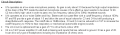
Hello, i am making an electronic stethoscope. But iam facing several problems in it.
I am using CM-01B Piezoelectric sensor . Here are the components of my circuit below.
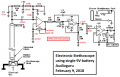
My circuit: 1) Charge amplifier using INA128P 2) Voltage amplifier using A620AN 3) BANDPASS Filter using TLC2272CP 4) LM386 AUDIO AMP Module 5) Speaker. I have also attached my circuit diagram.

Problems: I am not getting any lung or heart signals. But as i tap on the sensor. it shows amplified peaks on the oscilloscope but very low sound on the speaker. while in case of heart and lung iam niether getting sound nor output on oscilloscope. Below is my basic circuit diagram. i have adjusted the bandpass filter for frequency 50 to 180 Hz But that isnt shown here in the circiut diagram. Pre amplifier circuit is also adjusted so that initial gain is 1000 Hz.1729271356528.png
 

MisterBill2

Joined Jan 23, 2018
27,481
If you have the scope plugged in to the 3 conductor (stereo) jack it is disconnecting the speaker amplifier. That is, if the system is wired like this drawing. That might be part of the problem.

AND, with a crystal pickup like that, you probably need a high value resistor across the input 47K ohms or maybe 100 K ohms. That will serve as the DC path for the input bias current. That might be part of your problem.
Really, though, instead of tying half of the input to audio "ground", have the two inputs, pins 2 and 3, each with 47K to the Vcc /2 line. It is an instrument amp, NOT an opamp.
 
Last edited:

panic mode

Joined Oct 10, 2011
4,973
that should work fine for normal audio application, but i doubt it will work well here as the expected signal is weaker. and impedance as low as 47k or even 1MOhm may dampen the weak signal too much.
the circuit suggested in datasheet has input impedance that is several orders of magnitude higher.
and why spend $60-100 on a microphone if you are not going to spend $1 on circuit recommended for it?
 
Last edited:

MisterBill2

Joined Jan 23, 2018
27,481
I have not looked at the circuit shown in the data sheet.
And certainly the comment about the resistance was correct. I was thinking about the crystal microphones that I have used in the past, certainly a much greater output.
 

Thread Starter

Mariam Mansoor

Joined Oct 8, 2024
3
If you have the scope plugged in to the 3 conductor (stereo) jack it is disconnecting the speaker amplifier. That is, if the system is wired like this drawing. That might be part of the problem.

AND, with a crystal pickup like that, you probably need a high value resistor across the input 47K ohms or maybe 100 K ohms. That will serve as the DC path for the input bias current. That might be part of your problem.
Really, though, instead of tying half of the input to audio "ground", have the two inputs, pins 2 and 3, each with 47K to the Vcc /2 line. It is an instrument amp, NOT an opamp.
Hi thanks for your reply.
Problem is that iam not even getting the signal without the audio amplifer. When i just plug the oscilloscope at the output of my bandpass filter. i can't see a signal of heart or lungs. Is it a problem with my gain. or anything else. I have currently disconnected my Audio amplification circuit.
 

MisterBill2

Joined Jan 23, 2018
27,481
If the signal is "actually there" then the amplifier should be boosting it. Have you tried connecting the transducer output directly to the scope input? That might reveal a lot about what is happening. Or not happening.
Usually, with an amplifier of any kind, if there is no output, it is good to check and verify that there is an input of adequate strength.
 

panic mode

Joined Oct 10, 2011
4,973
here is link to the CM-01B datasheet.

and mentioned circuit is shown below. i have not tried to calculate input impedance but R4 is 100M so it is very high.
in comparison to 47k or 100k resistor that was proposed in post #2, this value is 5000x greater. and much greater than impedance of the oscilloscope input - typical probe is 1MOhm which in this case is still not much different than a short circuit. This is why you don't see anything when probing microphone. And you only hear noise once the microphone is abused (hit/dropped) to produce signal with much larger amplitude than usual...

for comparison look at the audio amplifier stage. typical speaker is 8Ohm. Your LM386 would not work either if the connected speaker was to have impedance that is 100x or 5000x lower than expected.

1729383795984.png
 

Thread Starter

Mariam Mansoor

Joined Oct 8, 2024
3
If the signal is "actually there" then the amplifier should be boosting it. Have you tried connecting the transducer output directly to the scope input? That might reveal a lot about what is happening. Or not happening.
Usually, with an amplifier of any kind, if there is no output, it is good to check and verify that there is an input of adequate strength.
hi thanks for your reply. iam getting heart signals now. Now can you please guide me on how to make an audio amplification circuit.. THE OUTPUT SHOULD BE AN AUDIO JACK FOR HEADPHONE CONNECCTION NOT SPEAKERS.
 

MisterBill2

Joined Jan 23, 2018
27,481
OK, The circuit you show in post #1 can work, not sure what is different. Just replace the speaker with an earphone connector jack. It may also benefit from adding a level control, which is shown in another thread that I will attempt to find. I did not see anything wrong with that circuit.
 

MisterBill2

Joined Jan 23, 2018
27,481
OK, and I have an answer: The circuit shown for that contact microphone tells us that it needs a voltage supply connected to the red wire and the amplified signal is present on the yellow wire. without the FET matching amplifier the output will not be much. AND, that circuit is INSIDE the pickup, and so you have no choice about using it. So a lack of microphone bias is a part of your problem.
 
Top