Facebook
 Google
 GitHub
 Linkedin
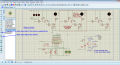
Well with Zero understanding pure Luck only I have got the Opto to switch on the MOSFET. I have no idea how or why. Now before I connect it to the LM3914 I would like to be sure that I am on the right track.
Attachments
-
9.2 KB Views: 22