Electronic circuit breaker

Thread Starter

boatsman

Joined Jan 17, 2008
187
Thank you Alec_t
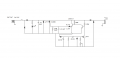
I don't know how much current the train draws. The output of the transformer is 12-0-12 at 2 amps. I have several 12VDC relays so if that's a better way I would be grateful for any assistance in using them. Incidentally would 1 amp diodes be sufficient for D1 and D2?
 

#12

Joined Nov 30, 2010
18,224
I's not clear to me where your circuit goes in relation to the OP's circuit since the current to the track is plus or minus DC. :confused:
The box marked, "unsafe loads" can contain anything that uses AC current...including the transformer for the train set, it's rectifiers and regulators, and DC lines to DC loads. My AC circuit breaker turns off the AC supply for anything that runs on AC. A transformer runs on AC. You might arrange whatever you want to run its current through the triac, depending on your needs and your skills.

The transformer in the upper left corner stays on, all the time. It provides DC to operate the latch-out circuit. In the original design, it was 24 VAC and it ran a bunch of other stuff, but that's irrelevant. I can connect any AC load from a relay, up to and including the heating and cooling controls for an entire building at the place marked, "Unsafe Loads".
 

crutschow

Joined Mar 14, 2008
34,469
Okay, here's my take on an electronic circuit breaker for the DC output of the train controller.
It may seem a little complex but that's because the DC current to the tracks is bipolar to provide the forward and reverse functions so it has to handle both output polarities.
R_Shunt is an added resistor in the ground leg of the track circuit.
The current through R_Shunt generates a small voltage which is made unipolar by the full-wave rectifier circuit consisting of U2 and U3.
When this voltage becomes high enough, SCR U1 trips and applies a voltage to the gates of M1 and M2. This turns them on and shorts the output of the control pot R2 (on the control circuit) to ground, shutting off the output voltage (and thus the current).
It requires two N-MOSFETs in series to control the pot output voltage since it's bipolar.
The SCR can be just about any small sensitive type.
The N-MOSFETs can also be just about any small devices.

The simulations shows that, for R_Shunt = 1Ω, the pot output (Vd) goes to ground (0V) when the current is plus or minus about 0.7A.
This can be varied by changing the value of R_Shunt.

V- and V+ are the DC voltages from the controller supply.

S1 and V2 represent a momentary NC PB switch to reset the SCR by momentarily interrupting its voltage.

Edit: Note that this circuit reduces the output to essentially zero volts unlike the current-limit circuit which can only reduce it to about 1 diode drop from ground, which could still generate short circuit currents well above the limit value.

Train Controller Current Limit.PNG
 

Attachments

Last edited:

crutschow

Joined Mar 14, 2008
34,469
The box marked, "unsafe loads" can contain anything that uses AC current...including the transformer for the train set, it's rectifiers and regulators, and DC lines to DC loads. My AC circuit breaker turns off the AC supply for anything that runs on AC. A transformer runs on AC. You might arrange whatever you want to run its current through the triac, depending on your needs and your skills.

The transformer in the upper left corner stays on, all the time. It provides DC to operate the latch-out circuit. In the original design, it was 24 VAC and it ran a bunch of other stuff, but that's irrelevant. I can connect any AC load from a relay, up to and including the heating and cooling controls for an entire building at the place marked, "Unsafe Loads".
Okay.
So I guess, in the OP's circuit, you would put it between the circuit ground and the transformer center-tap ground. That sound right?
 
Last edited:

#12

Joined Nov 30, 2010
18,224
Personally, I would take the circuit in post #4 and put the primary of T1 in the "unsafe loads" box as the simple way to approach this. Mostly because I'm busy sucking Happy Meals out of the rear air conditioner of an SUV today. You wouldn't believe what 10 years of chauffeuring 3 children around in a car will do to its filth factor!!! I'm dumping the wash water out of the wet&dry vac where there is no lawn because I believe it would kill the grass if it touched any.:eek: Holey Mother of Dog! Third time rinsing the soap out and the rinse water is as clear as Coca-cola.:( At least it smells a lot less like puppy after 4 days of cleaning!

The idea for the AC fuse came to me when I saw the Air conditioner re-start Delay circuit (posted below). There is a pile of parts inside a full wave bridge. That makes the delay function a pulsed DC circuit which is inside the loop of the full wave bridge. In the AC fuse circuit, There is a pile of parts detecting a current and deciding whether to turn off the triac. So, the AC fuse doesn't go inside any train controller loop, the train controller, in whole, goes inside the "AC fuse" current detector loop.

Yeah, I know we think differently, and you're really going to have to cut me some slack on how I use words, but I'm trying. If I had all day, I could probably figure out how to use the train controller to make some DC to operate the triac controller and over-current detector. That's how I designed this in the first place, except all my loads were AC. The train controller has DC loads. Only after I got finished designing did I realize that I could make the over current detector stand alone and put anything I want in the path of the triac, as long as it's an AC load.
 

Attachments

crutschow

Joined Mar 14, 2008
34,469
So if put this circuit in the primary (mains) side then will you need to add add another transformer for power or would you try to run it directly off the mains?
Of course discussing main's circuits on this forum is problematic. :rolleyes:

Another consideration is that the diode-capacitor power supply will draw peak AC currents that are much larger than the average DC output.
 

GopherT

Joined Nov 23, 2012
8,009
Of course discussing main's circuits on this forum is problematic. :rolleyes:
According to TOS, only for LED circuits. People discuss 480 VAC 3-phase motor control circuits with no problems.

And transformer-less power supplies. This clearly has a transformer.
 
Last edited:

#12

Joined Nov 30, 2010
18,224
So if put this circuit in the primary (mains) side then will you need to add add another transformer for power or would you try to run it directly off the mains?
The origin of the DC supply for the triac gate must not be defeated by the AC fuse circuit. I thought about taking DC from the train controller to run the AC fuse circuit, then realized that after the mosfet times out, the primary will not start up until there is current available to the triac gate. This might be overcome by creating a DC drive for the mosfet gate from the power side of the 120 VAC line. This is a prohibited subject, so I will not describe the circuit, but I'm sure you can see several ways to do it.

The, "allowable way" is to use another transformer which is not defeated by the AC fuse. There are other ways. wink wink.

Still, a black box containing a low voltage transformer, DC supply, triac, current detector, conparator, and latch, could be a standalone product with a power cord on one end and a receptical on the other end. Any load could be plugged in provided that an overcurrent limit adjustment is provided and a method is devised to allow inrush current if that becomes a problem. The circuit I needed this for had no DC loads other than the triac gate and so inrush current was not a consideration.

The concept has been presented in public. Make of it what you will. Modify it any way you want to serve your needs.

It is even conceivable to start with a normally on AC component that must be switched off by the time-out circuit. That would negate the need for a DC supply to allow restart.

Yet another idea..if the timeout is 1 second, a capacitor might be used to supply the triac gate. You would need the gate milliamps required by the triac of your choice for just about one second
 
Last edited:

shortbus

Joined Sep 30, 2009
10,045
DC current to the tracks is bipolar to provide the forward and reverse functions so it has to handle both output polarities.
Is it really bipolar? Thought train power supplies just reversed polarity, like in a H-bridge, not the positive/negative the OP stated.
 

Thread Starter

boatsman

Joined Jan 17, 2008
187
The circuit I want to use has a pot that sends a current to either a pnp or an npn Darlington. It means that the voltage goes from plus to minus via zero. Other systems use a dpdt switch to change train direction with the result that if the engine is travelling forwards at top speed and it is suddenly reversed it's more than likely that it would cause a derailment and a short across the tracks.
 

crutschow

Joined Mar 14, 2008
34,469
Is it really bipolar? Thought train power supplies just reversed polarity, like in a H-bridge, not the positive/negative the OP stated.
What's the difference between bipolar voltage and reversed polarity voltage?
To me they are the same thing, at least in the context of the OP's problem. :confused:
 
Last edited:

crutschow

Joined Mar 14, 2008
34,469
The circuit I want to use has a pot that sends a current to either a pnp or an npn Darlington. It means that the voltage goes from plus to minus via zero. Other systems use a dpdt switch to change train direction with the result that if the engine is travelling forwards at top speed and it is suddenly reversed it's more than likely that it would cause a derailment and a short across the tracks.
So, the question is, can you design the circuit with a sufficient heat sink to use a current-limit circuit (which is generally simpler) or do you need to use a circuit-breaker approach, such as posted by myself and #12?
 

#12

Joined Nov 30, 2010
18,224
Another thought just crossed my head...a PTC thermistor. I saw a car with a PTC in the power door lock circuit. That must need several amps for less than a second to slam 4 or 5 lock solenoids. One of the lock buttons got stuck and the PTC knocked the current down to 150 ma for a week. Dead battery, several times before the car was brought to me, but it didn't catch on fire.
 

Videostar

Joined Feb 4, 2013
14
The circuit I want to use has a pot that sends a current to either a pnp or an npn Darlington. It means that the voltage goes from plus to minus via zero. Other systems use a dpdt switch to change train direction with the result that if the engine is travelling forwards at top speed and it is suddenly reversed it's more than likely that it would cause a derailment and a short across the tracks.
Hi, I too am into controlling DC model trains. The simplest option for you is to go to "www.digikey.com" and search for "Polyswitch fuse". This device is a compact self-restting fuse (the size of a ceramic capacitor but also available as SMD) and available in currents from 50mA up to 30 A (!). I use a 4A unit for the largest scale I model. When a short-circuit occurs it trips to a small holding current and is reset by removing the supply or turning the controller to "stop". Nice and simple to use - connect in series with the feed to the track - and it's also cheap.
 

TWRackers

Joined Dec 29, 2008
41
Our club (Japan Rail Modelers of Washington DC) addressed this problem using a 4-circuit box with the PTC polyfuses. Our large portable layout has four track loops (two for Shinkansen and two for slower trains). In series with the DC throttle for each track is a polyfuse, 1.3A for the faster trains and 0.6A for the slower. In parallel with each polyfuse is a small full-wave bridge rectifier; across the +/- terminals is an LED with dropping resistor sized for max 12V DC. Under normal operations the polyfuse is low resistance, so the track current passes through it and not through the rectifiers and LED. When the current limit is exceeded, the polyfuse goes to high resistance and the track current (now limited by the LED and resistor) lights the LED indicating a fault. To reset, all you have to do is power down, remove the short, wait a second or two for the fuse to reset, and power up again.
 

TWRackers

Joined Dec 29, 2008
41
@TWRackers
Can you post a circuit of your layout? I am using N gauge.
Should be able to do that this evening. Before the ball drops and we break out the plum wine, that is. ^_^

(We're doing N gauge as well. 1:160 for Shinkansen, 1:150 for everything else. Japan uses two different rail gauges on the real trains.)
 

TWRackers

Joined Dec 29, 2008
41
Should be able to do that this evening. Before the ball drops and we break out the plum wine, that is. ^_^

(We're doing N gauge as well. 1:160 for Shinkansen, 1:150 for everything else. Japan uses two different rail gauges on the real trains.)
Schematic for electronic circuit breaker as used by JRM-DC (see my earlier posts). The four diodes actually represent a single 4-lead full-wave bridge rectifier part. Doesn't need to be large, you'd be hard pressed to get an N-gauge model train to draw even 2 amps, unless you have a lot of locomotives running together.

Ours was built on a small perfboard and mounted inside a smallish Really Useful Box, with power leads terminated with PowerPoles coming out two sides, and the LEDs mounted in the lid. I'd send a photo but it's stored with the layout's wiring harnesses in another club member's basement.

We built this circuit after a running train at a public show caught a point and hung there for several minutes before someone noticed. The short circuit that resulted partially melted a truck/bogie on the locomotive.

TrackPowerBreaker_schem.jpg
 
Top